9500 MXC User Manual
3DB 23063 ADAA - Rev 004 July 2007 Vol. IV-10-5
the NMS network into which the Node/Terminal is to be installed has been
segmented for OSPF area operation, its area number must be entered. Otherwise
leave unchecked.
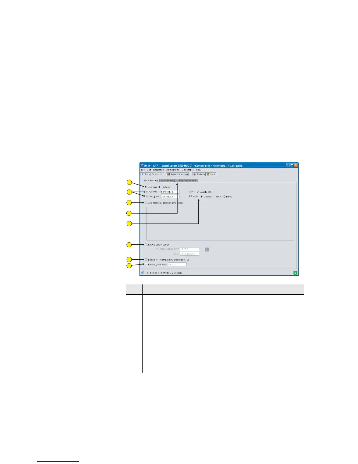
Figure 10-1 shows a typical IP Addressing screen. The example shows entry of a
single IP address, and no selection of dynamic routing, indicating static routing
has been chosen. To view other screen selections refer to:
• Figure 10-2 on page 10-7 for a Static Routing screen.
• Figure 10-3 on page 10-10 for an Interface Addressing screen.
Figure 10-1. Single IP Address Screen
Item Description
1 The single IP address option is selected.
2 User defined fields for the IP addresses, and mask.
3 Click to select the Interface addressing (advanced addressing) option.
4 Tabs provide access Static Routing and Trap Destination screens.
5 Click to enable dynamic routing, OSPF or RIP.
6 Click to enable the DHCP Server option for CT PC connection.
7 Click to enable NMS access via an XP4 NMI connection (For use where a 9500
MXC Node/Terminal used to extend a network from one or more XP4 links).
1
2
3
4
5
6
7
8