Chapter 10. Networking Configuration
Vol. IV-10-10 Alcatel-Lucent
selection enabled on a per-interface basis.
The screen opens with line entries for the Ethernet port, the Link(s), and the V.24
maintenance port. For the 9500 MXC Node the number of Link lines match the
number of links installed (non-protected and protected each count as one link).
For a ring configuration both links are shown, with the Link lines replaced by
reference to RING 1:RAC 1 NMS, and RING 2:RAC 2 NMS.
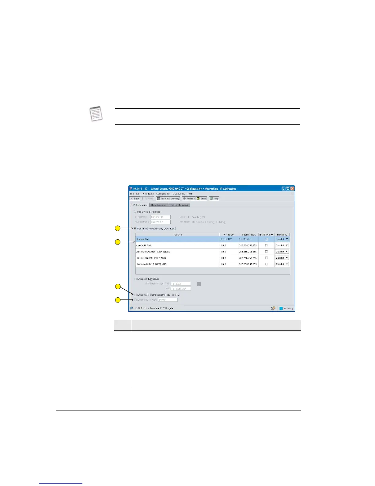
Figure 10-3 shows an example IP addressing screen for a 9500 MXC Node.
Figure 10-3. Interface Addressing Screen
Interface IP addressing and routing options should only be used under guidance
from the network administrator.
Item Description
1 The Interface Addressing option has been selected.
2 User-defined fields are provided for IP address, mask, OSPF and RIP. The
example shows the V.24 interface and links with default settings (not
configured).
3 Click to enable NMS access via an XP4 NMI connection.
4 Use with an OSPF routing selection to define the OSPF area.
1
2
3
4