Thermocouple Measurement/Simulation, Connections and Troubleshooting
MC4 User Guide 113
Thermocouple Measurement/Simulation, Connections and
Troubleshooting
To accurately measure the thermovoltage caused by the
temperature to be measured, the second thermovoltage caused by
the Reference Junction needs to be compensated. This is done
using one of the Reference Junction compensation methods
described in the subsequent chapters.
The Reference Junction compensation method has to be chosen
both when measuring and simulating thermocouples.
Internal Reference Junction
MC4's Internal Reference Junction makes thermocouple
measurement/simulation easy. No external connections are
required, just connect the thermocouple or a thermovoltage receiver
directly to MC4's "T/C" terminals. To select this compensation
method, set the window's Function to field "
T/C Sensor
Measurement
" or "
T/C Sensor Simulation
", make sure the
Unit
is a temperature unit and set the
RJ Mode
field to "
Internal
".
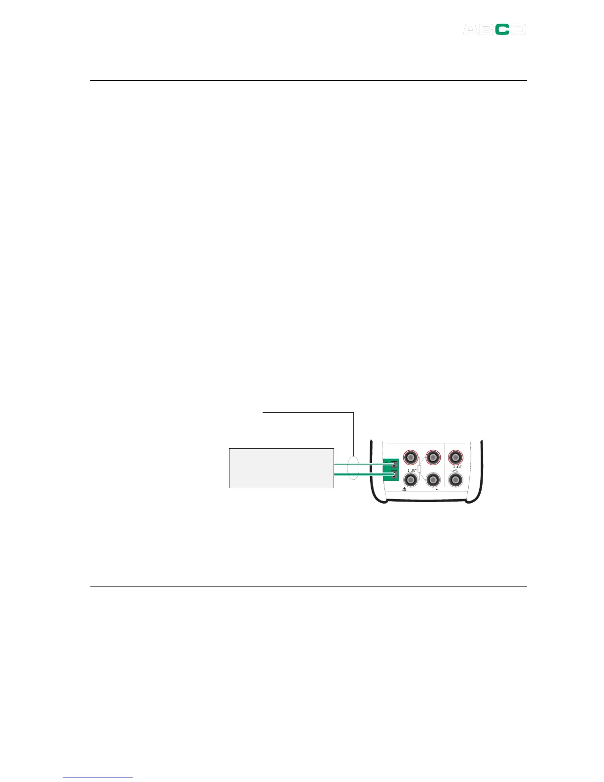
Connection when measuring/simulating thermocouples using
Internal Reference Junction Mode:
M e a s u r e
M a x 6 0 V , 3 0 V , 1 0 0 m A
s e n s e
R , R T D R m e a s
V , I
,
V , I ,
T e m p e r a t u r e / G e n e r a t e
T / C
m V
T / C s e n s o r
o r a
T / C s i g n a l r e c e i v e r
T / C m a t e r i a l s
( T / C , e x t e n s i o n o r
c o m p e n s a t i o n w i r e s )
Refer to the Technical Data in Appendix 1 for specifications
concerning the Internal Reference Junction.
See also
External Reference Junction on page 114

 Loading...

