Resistance and RTD Measurement, Connections
MC4 User Guide 119
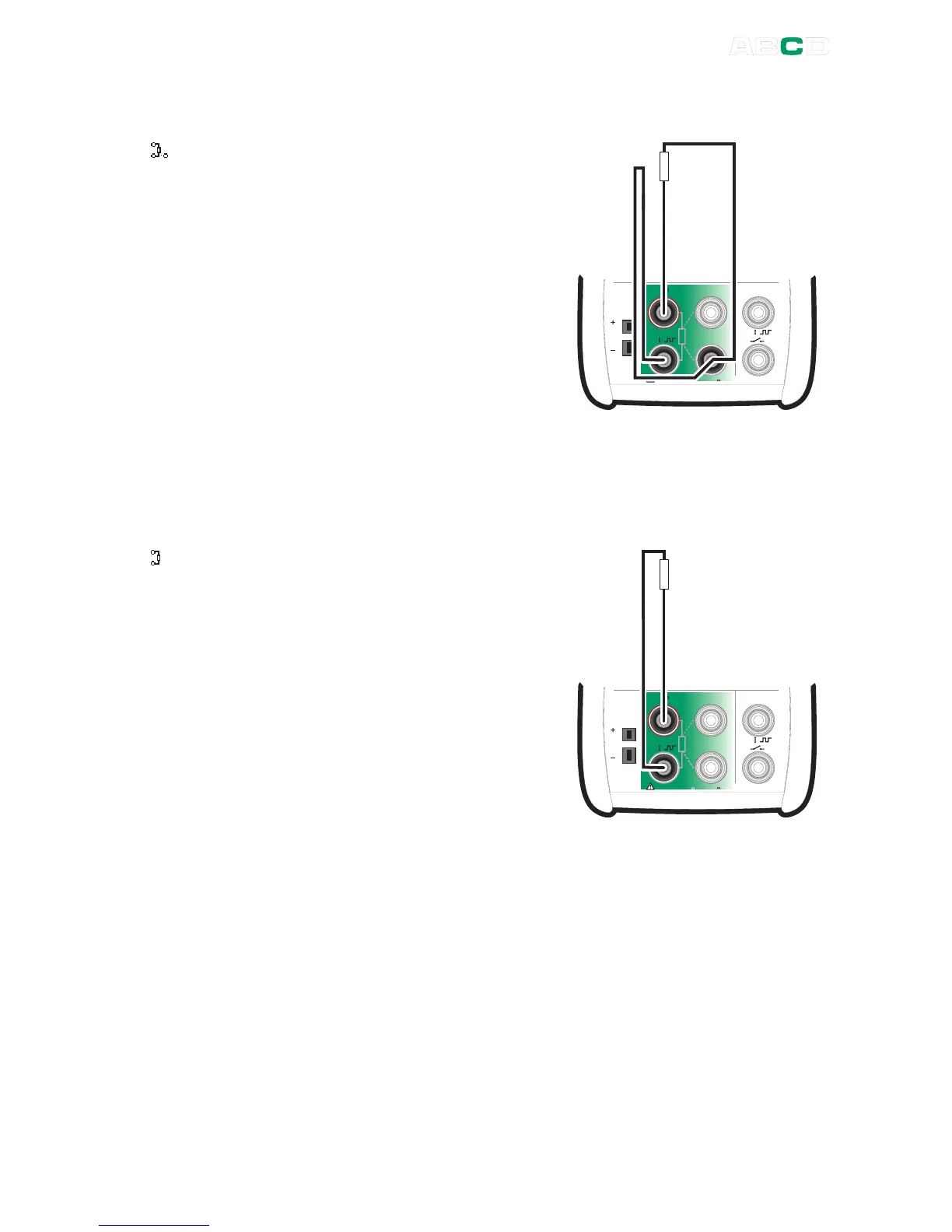
Using a Compensation Loop
When the compensation loop
wiring system is used, MC4
displays the symbol shown on the
left.
MC4 sources current through the
resistor and the compensation
loop from the two left side
terminals. MC4 measures the
voltage drop across the entire
current loop and across the
compensation loop.
M e a s u r e
M a x 6 0 V , 3 0 V , 1 0 0 m A
T / C
m V
s e n s e
R , R T D R m e a s
V , I ,
V , I ,
T e m p e r a t u r e / G e n e r a t e
If the compensation loop and the connection wires of the resistor are
identical, MC4 can compensate for the resistance of the connection
wires.
2-wire System
When 2-wire system is used, MC4
displays the symbol shown on the
left.
Calibrator sources current through
the resistor and measures the
voltage drop across the same
terminals.
The result is acceptable, if the
resistance of the connection wires
is significantly smaller than actual
measured resistance.
M e a s u r e
M a x 6 0 V , 3 0 V , 1 0 0 m A
T / C
m V
s e n s e
R , R T D R m e a s
V , I ,
V , I ,
T e m p e r a t u r e / G e n e r a t e
Hint!
To minimize the effect of connection wires in 2-wire system
measurement, use deviation measurement presented on page 87 as
follows:
Measure the resistance of only the connection wires. Set the
measured value as the Measure Deviation from value. Then the
resistance of the connection wires is subtracted from the total
resistance and the displayed deviation value is closer to the
resistance meant to be measured.
 Loading...


