Tools Menu
82 MC4 User Guide
Error %
Error Percentage display compares the measurements of the two
windows based on entered measurement range values. The window
the Error Percentage display was invoked from is considered the
"output" of the instrument and the other window the "input".
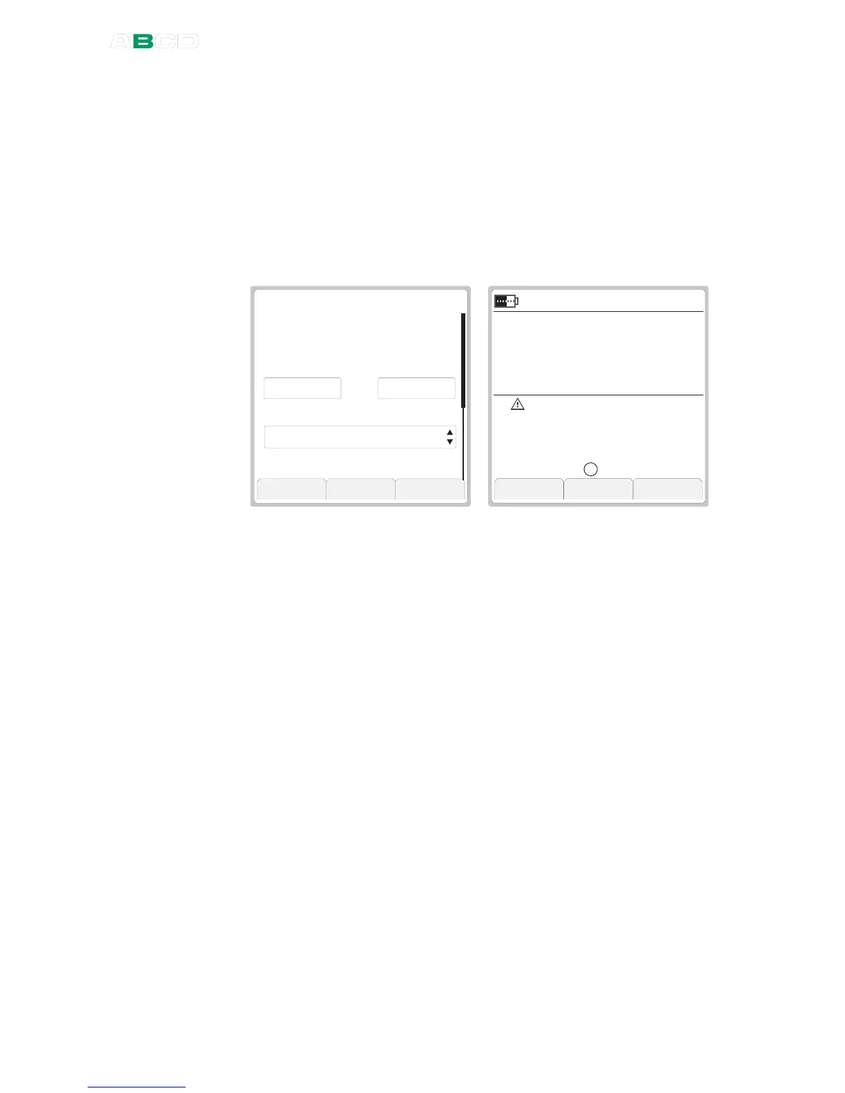
The Error Percentage value is shown in the "output" window and the
actual "output" signal is by default shown on the additional info row
as seen in the rightmost picture.
5 . 9 6
O u t p u t
E R R O R %
T r a n s f e r F u n c t i o n
S t o p C a p t u r e O k
k P a
G a u g e
I N T
0 . 9 8
I n p u t R a n g e ( 0 % . . . 1 0 0 % )
L i n e a r
0 . 0 0 0 1 0 0 . 0 0 0
I n p u t
m A
S u p p l y : O n
. . .
When Error Percentage display is active, the words "
Error %
" is
displayed after the warning triangle.
To configure the error percentage display (and also the other types
of error displays) you need to enter input and output range values to
both windows.
In addition to the range you may also set the
Transfer Function
(Input/Output relationship). Default value is:
Linear
.
The display resolution may also be edited, if needed.
Notes.
If anything else was selected for display on the additional info row,
the main measurement of the Error percentage window replaces the
previous additional info data.
Also: if you select two other items to be displayed on the additional
info row while an error display is active, the second item replaces the
windows' main measurement data. Beware of the problems that
may result in not seeing the true measurement value.
For help on making Custom Transfer Functions, see Part C,
chapter Custom Transfer Functions on page 103.
 Loading...


