RTD Sensor Simulation
MC4 User Guide 61
RTD Sensor Simulation
In RTD sensor simulation MC4 mimics an RTD. The instrument
under test generates the current for the RTD measurement. MC4
controls the voltage across its terminals so that the resistance
(voltage to current ratio) corresponds to the simulated temperature.
Function:
RTD Sensor Simulation
Also check the
Sensor
setting. Make sure you select the same
sensor type than the connected instrument requires. Otherwise your
simulation is useless. For information on creating custom Platinum
Resistance Temperature (PRT) type RTD sensors, see Part C,
chapter Custom PRT Sensors on page 106.
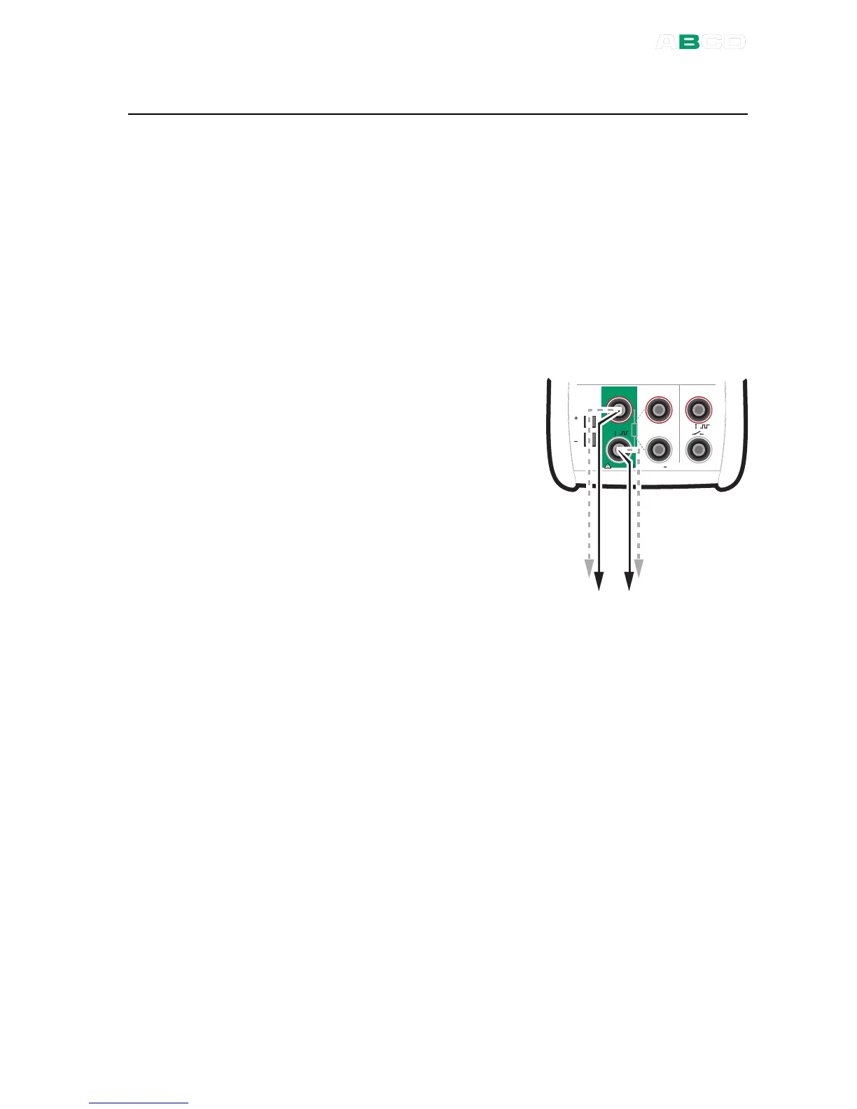
The correct resistance value is
between the resistance simulation
terminals of the calibrator. Use of 2-,
3- or 4-wire connection is up to the
receiver instrument. Use only the two
leftmost R, RTD terminals with every
wiring option. Connect the possible
third and fourth wire according to the
requirements of the connected
instrument, but use only the two
leftmost R, RTD terminals.
By default the additional info row at the bottom of the window
displays the resistance MC4 is simulating while performing RTD
simulation. More of additional info row on page 90.
 Loading...


