608/641 Bosch Rexroth AG | Tightening Technology 3 608 878 300
System 350 | 3 608 878 300/2019-03
7.6.6.2 Nutrunner docking configuration
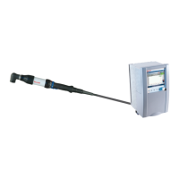
The "Nutrunner docking" function can be used to change the tightening tool (ErgoSpin hand-held
nutrunner or Rexroth tightening spindle) during normal operation without long waiting times.
Initial commissioning to configure the function Nutrunner docking:
1. Set the Tightening channel configuration to Automatic.
2. Activate the additional function nutrunner docking via the respective option Nutrunner docking.
3. Carry out the following so that the system detects the Rexroth tightening spindle when it is
connected:
Configure the Rexroth tightening spindle via the BS350 for the first time.
When the Tightening channel configuration is sent to the controller, the spindle configuration
is also stored in the measurement transducer on the Rexroth tightening spindle.
When the tightening tool is connected again, the system imports the configuration from the
Rexroth tightening spindle.
7.6.6.3 Sending/saving data
The created tightening application has to be sent to the KE. It can also be stored as a file on the PC (see
Sending and saving (page 542)).
7.6.6.4 Loosening tightened bolts
Already tightened bolts are loosened with program no. 99 (Ccw). The tightening application only defines
the tightening channels in which program no. 99 is executed.
Activating Loosen in the sequence test (see Sequence test via theBS350 (page 582)) always
simultaneously starts loosening program no. 99 in all the tightening channels. Proceed according to
Defining a tightening program (page 577) to create and send a loosening program.
7.6.7 SE PLC assignment table
For information on the SE PLC assignment table, see Configuration SE/CS PLC assignment table
(page 580).
The typical time required for docking is 3 to 4 seconds. In case of unfavorable boundary conditions, this
time may be extended. For example, excessive connection cycles at connector or socket contacts may
lead to extended docking times.

 Loading...