121
Bruker Optik GmbH IFS 125M User Manual
Maintenance 6
4 • Loosen the clamp screw located between
the two spring-loaded bolts (5 in figure
6.9).
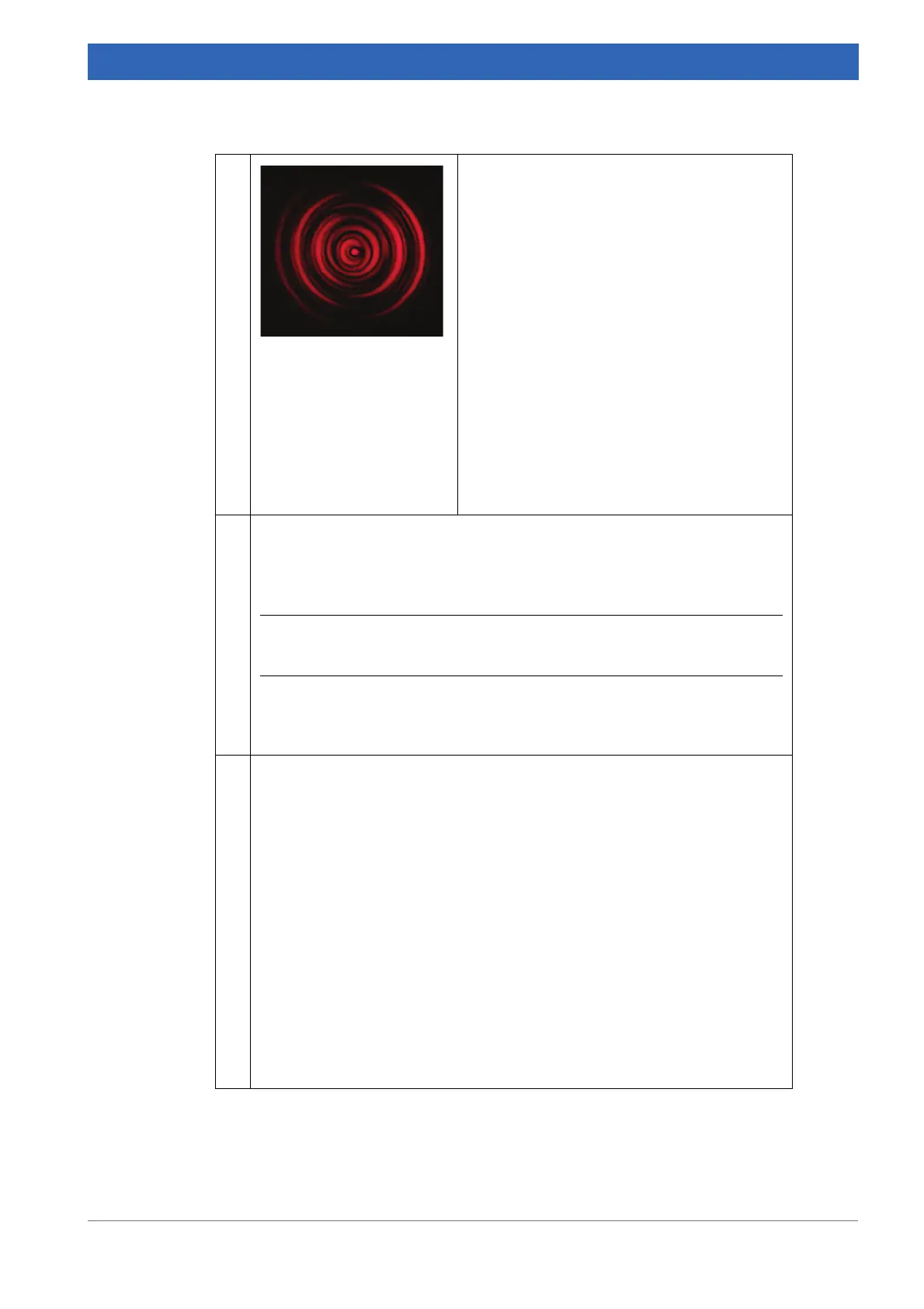
• Adjust screws (4 in figure 6.9), which causes
a x-y shift, so that the observed diffraction
pattern is at maximum brightness.
☞ If required, re-adjust the pre-load by
means of screws (5).
• Adjust screws (1 in figure 6.9), which causes
a tilt, to achieve a (nearly) concentric diffrac-
tion pattern.
☞ If the pre-load of any screw (1) gets too
high or too low, the tension can be cor-
rected by means of the screw (2) which is
diagonally opposite.
• If necessary, the x-y and tilt adjustments
have to be repeated.
• Remove the alignment tool.
5 • Mount the fiber patch cord.
➣ As the fiber is very sensitive, be careful by putting the fiber on the cou-
pler. Do not use too much force and turn the fiber slightly (at the plug)
while guiding the ferrule into the socket.
i The whole receptacle is mounted at a 3.5° angle, so the ferrule must be
tilted at that angle, too.
• Make sure that the key at the plug points into the direction of the notch at
the receptacle.
• Fix the lock nut only hand-tight.
6 You should see a light beam (at least dim) emitting out of the fiber. You can
watch the beam on a white piece of paper.
• If available, mount the fiber collimator tool with integrated polarizer and Si-
diode at the fiber end.
• Rotate the integrated Si-diode until a maximum intensity is read. Lock the
position. If the tool is not available, use the power-meter or Si-diode to
monitor the intensity (P
out
).
• Turn screws (4) slightly one by one to increase the intensity.
☞ If required, re-adjust the pre-load by screws (5).
• Adjust the tilt of the coupler. Use screws (1) one by one to change the tilt
and maximize the intensity.
☞ If required, re-adjust the pre-load by the screw (2) located diagonally
opposite.
• Repeat the x-y and tilt adjustments successively until you achieve a power
P
out
a
, which is at least 65% of P
in
b
.
Table 6.31: Readjusting fiber-coupling head
 Loading...


