69
Bruker Optik GmbH IFS 125M User Manual
Maintenance 6
6.2.2 Quick check in OPUS
1 Check the modulated signals in OPUS:
☞ On the Measure menu, select the Optics
Diagnostics command.
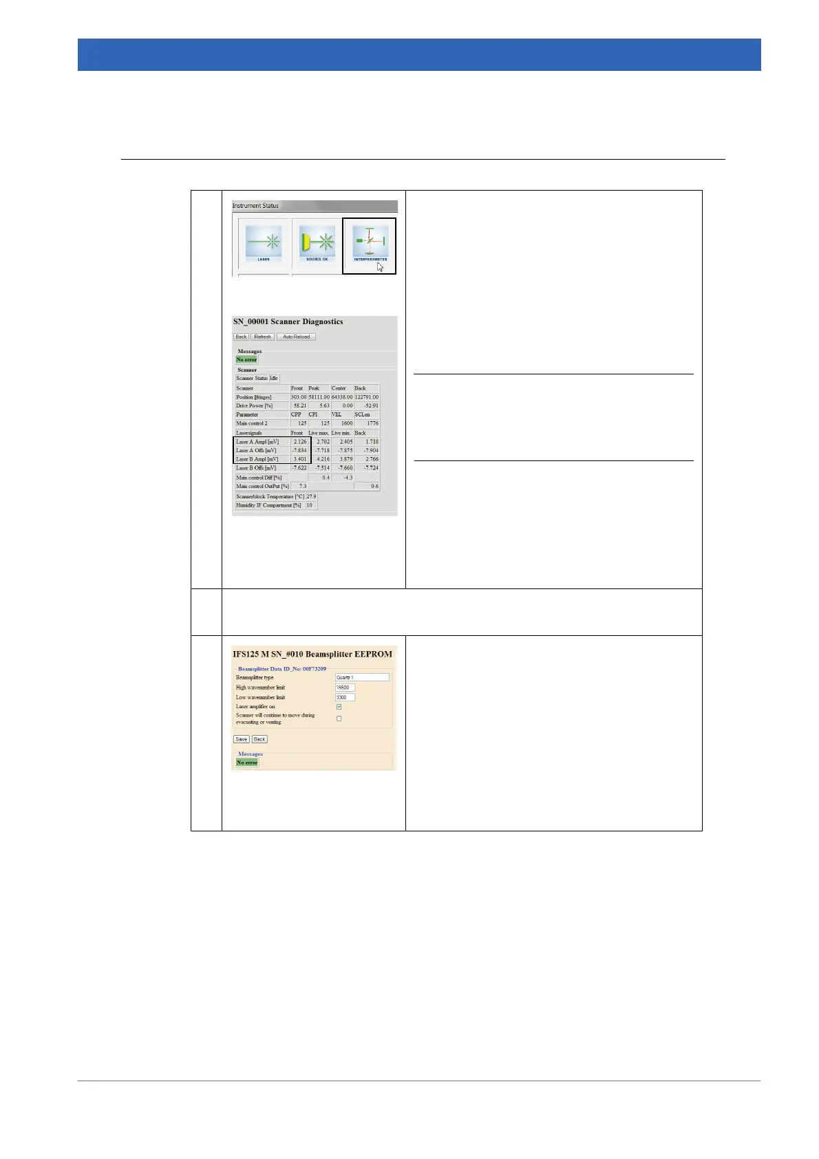
☞ On the Instrument Status dialog click the
Interferometer icon.
☞ On the dialog shown, click the Service
Info button to open the Scanner diagnos-
tics page.
i Laser A (or B) Amplitude [mV] is the
detected peak-to-peak voltage. Laser A (or
B) Offs [mV] is the detected mean (or DC)
voltage.
For both laser signals applies the following:
• -10,000 < Offs - Ampl/2
Offs + Ampl/2 <10,000
Ampl >2,000
The values are only determined at the current
scanner position, which is usually close to
zero path difference.
2 The laser beam must be properly transferred to the two laser detectors. Nor-
mally, there is no re-adjustment required by the user.
3 The laser amplifier has two gain settings,
which are selected by a corresponding bit in
the EEPROM of the beamsplitter. This kind of
setting can only be accessed via the WEB
interface. Details are described in
chapter
8.3.3 Edit hardware configuration.
If the signal amplitude is too small and the low
gain is in effect (amplifier off), write the high
gain setting permanently into the beamsplitter
(and vice versa).
Table 6.1: Quick check in OPUS
 Loading...


