71
Bruker Optik GmbH IFS 125M User Manual
Maintenance 6
6.2.3 Signal decrease over optical path
The decrease of the peak-to-peak signal amplitude over the full optical path should be
less than 35%.
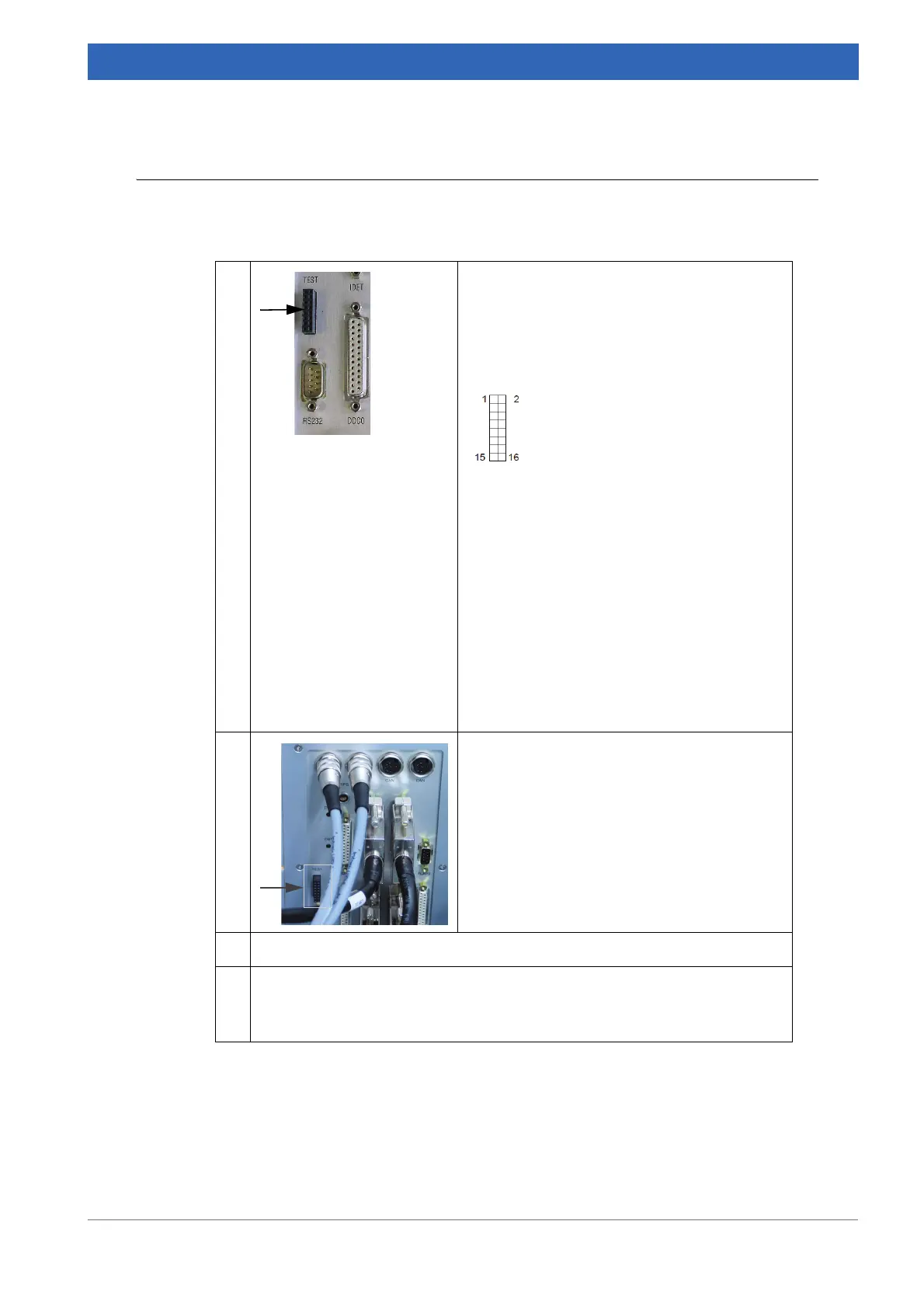
1
Connect a dual channel oscillograph
a
to the
TEST adapter located on the mobile electron-
ics unit.
Pin assignment of TEST adapter:
1 LASA (Laser A)
2 AGND (Ground for 1 + 3)
3 LASB (Laser B)
4 FWDLSW
5 DGND
6 BWDLSW
7 LASXAF
8 DGND
9 SCM+ (Scanner Voice Coil)
10 SCM- (Scanner Voice Coil)
11 DCANA
12 - 16 Spare
➣ Do NOT short-circuit any pins!
2 Connect one end of the laser signal test cable
to the Test connector located on the electron
-
ics unit.
3 Connect the other end of the laser signal test cable to the oscillograph.
4 • On the OPUS Measure menu, select the Optic Setup and Service com-
mand.
• Click the Control Panel tab
b
.
Table 6.2: Signal decrease over optical path
 Loading...


