76
IFS 125M User Manual Bruker Optik GmbH
Maintenance 6
6.2.5 Phase
The phase between laser A and B signals should be 90 +/- 45°. Check in regular scan-
ning mode (after pressing Reinit Scanner) with a dual channel oscillograph connected to
the test adapter.
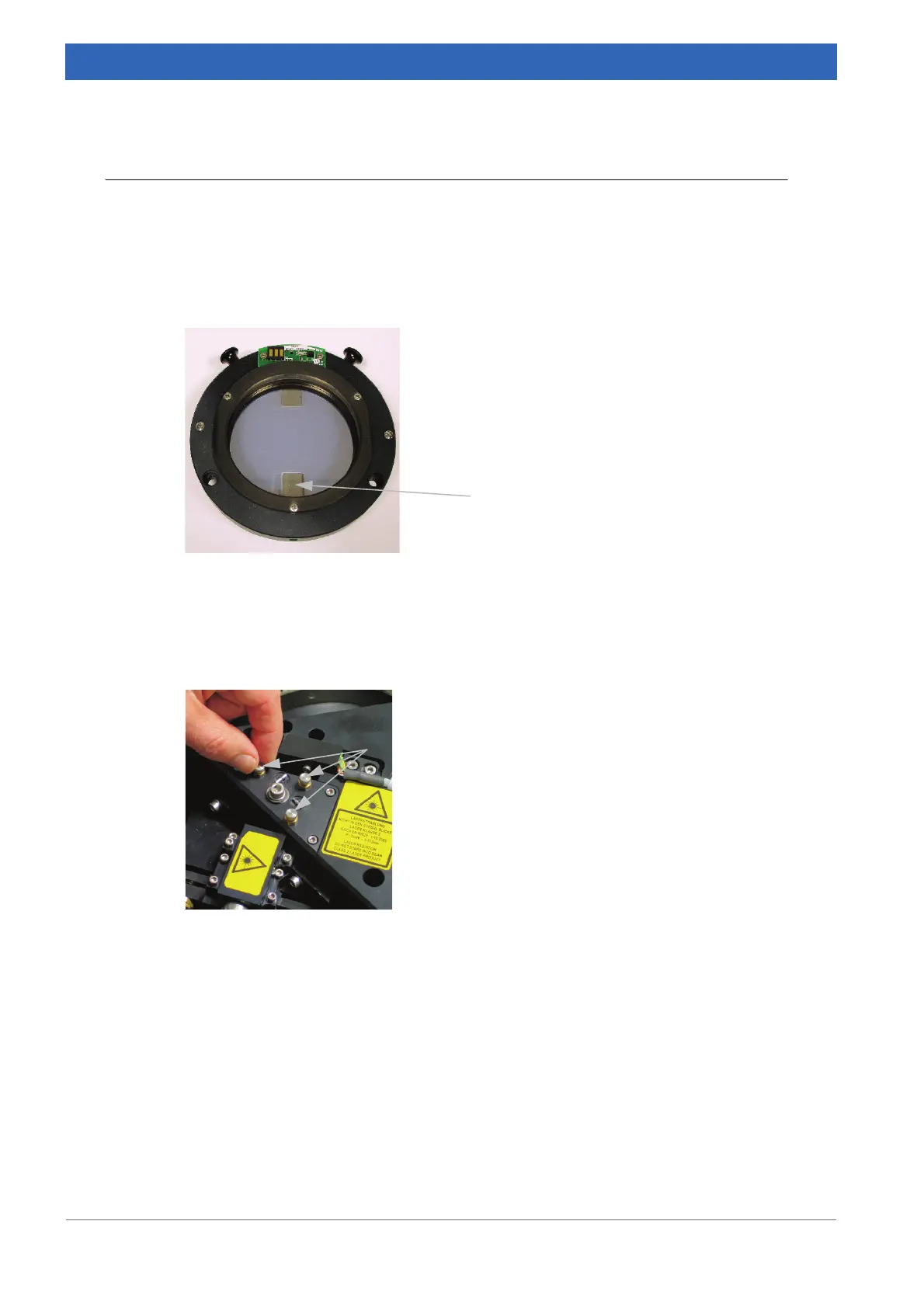
Make sure that the laser beam passes properly through the lower rectangular area (A in
figure
6.1) of the beamsplitter, which is specifically coated for the laser beam.
To slightly adjust the beam height turn all 3 adjustment screws of the laser deflection unit
to the same direction. Observe the laser signals on an oscillograph. Maximize the ampli
-
tude as described in chapter 6.2.4.
There is no way to adjust the phase, i.e. if the phase is out of specification, the particular
beamsplitter has to be replaced (chapter
5.8).
Figure 6.1: Beamsplitter area for the laser beam
A
Figure 6.2a: Adjustment screws of the laser
deflection unit
 Loading...


