182
IFS 125M User Manual Bruker Optik GmbH
Connection Ports 10
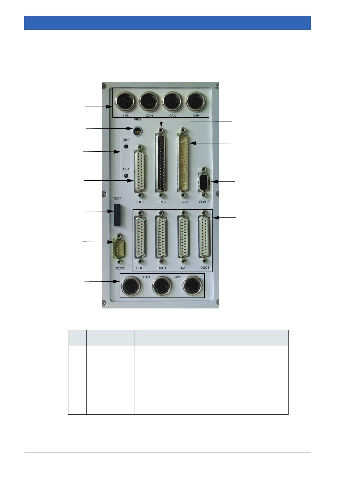
10.1 Flange panel
Component Definition
A CAN bus The CAN bus connectors on top of the flange panel are
used for the automation unit control to the different com
-
partments of the spectrometer, e.g. source, interferome-
ter, sample, detector compartment).
There is no specific order to be observed when using the
CAN bus connectors, i.e. they can always be inter
-
changed.
B PIPS port The PIPS port is not used with IFS 125M.
Table 10.2: Ports on flange panel
Figure 10.2: Flange panel
H
I
J
K
A
B
C
D
E
F
G
 Loading...


