130
IFS 125M User Manual Bruker Optik GmbH
Troubleshooting 7
7.5 No interferogram observable in Check Signal mode
In this case, it is assumed that no interferogram will be displayed on the Check Signal
tab on the OPUS Measurement dialog.
Assuming that the spectrometer can be accessed and that there is an optical connection
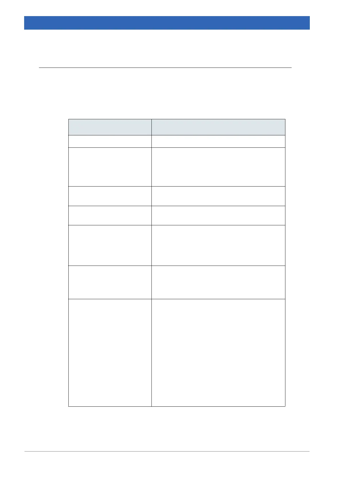
between the interferometer outlet and detector inlet, the problem can be caused by:
Possible causes Solutions
No optics connected See chapter 7.7.
OPUS status light is gray Check the optical bench URL.
☞ On the OPUS Measure menu, select the
Optic Setup and Service command.
☞ Click the Optic Bench tab.
Wrong measurement para-
meters
Use the measurement parameters as described in
appendix
C.
Optical path blocked Check whether any accessory blocks the IR
beam.
Detector not or incorrectly
installed. The following mes
-
sage pops up: Device not
connected. No analog board
selected.
In case of manually changed detectors:
• check whether the detector is properly inserted
into its holder.
• check whether the DDC cable is connected
properly (see chapter
3.6.1).
No or wrong detector selected • On the OPUS Measure menu, click the
Advanced Measurement command.
• Click the Optics tab to select the correct detec-
tor.
Wrong peak position saved • On the OPUS Measure menu, select the
Advanced Measurement command.
• Click the Check Signal tab to determine and
save the correct peak position:
☞ Use the < and > scan range buttons to shift
the start position of the scanner.
☞ After each click, wait until a new interfero-
gram is displayed. Once the peak is found,
click the Save Peak Position button.
☞ If the true peak position is too far away from
the saved peak position, determine the true
position from a Sample Single Channel mea-
surement as explained in chapter 8.3.3, Spe-
cial commands A and B.
Table 7.4: No interferogram observable
 Loading...


