22
IFS 125M User Manual Bruker Optik GmbH
Installation 3
3.6 Connecting procedures
3.6.1 Connecting cables to the mobile electronics unit
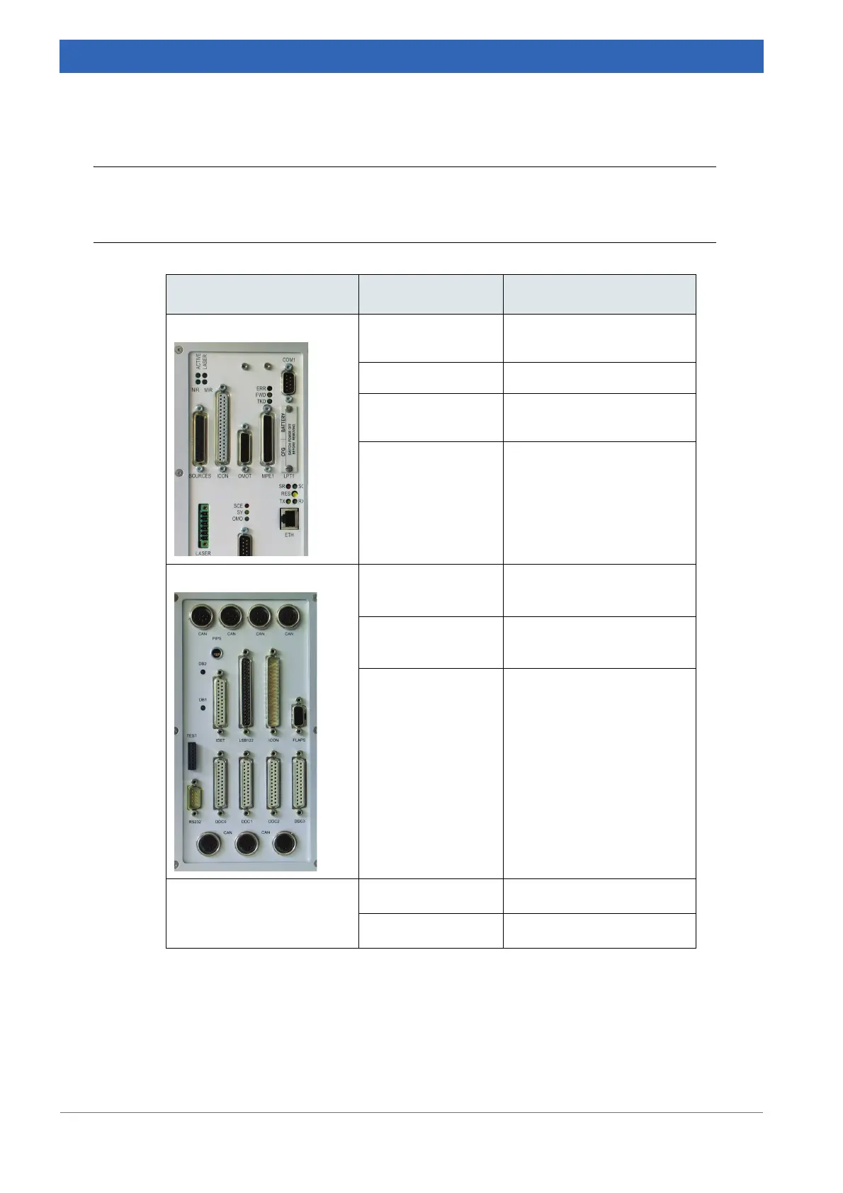
On panel: Connect... ...with...
Electronics: LASER cable from HeNe laser
(located in upper panel)
ICON ICON at flange panel
Sources receptacle at calibration
source
OMOT OMOT at left electronics
box
Flange:
DDC0
a
DDC
a
at right electronics
box
a. All DDC receptacles are equivalent, no specific order has to be observed.
DDC1
a
DDC
a
at right electronics
box
LSB122 LSB at the left electronics
box
CAN
b
b. All CAN receptacles are equivalent, no specific order has to be observed.
CAN at left electronics box
CAN
b
CAN at right electronics box
Table 3.5: Connecting cables to the mobile electronics unit
 Loading...


