183
Bruker Optik GmbH IFS 125M User Manual
Connection Ports 10
C DB1/2 LED The green DB1 LED is used to see whether data commu-
nication is performed between the flange panel and elec-
tronics panel. The red DB2 LED is reserved for future use.
If the DB1 LED is ON, data are sent from the flange panel
via CAN bus to the electronics panel. In case of a suc
-
cessful data communication the DB1 LED is switched off
again. The DB1 LED has to flash every now and then.
Sources and other accessories are controlled via the
flange panel.
D IDET port The IDET port provides a connection to the detector. The
IDET port is functionally compatible to the DDC ports (0 -
3). The IDET abbreviation means Internal Detector.
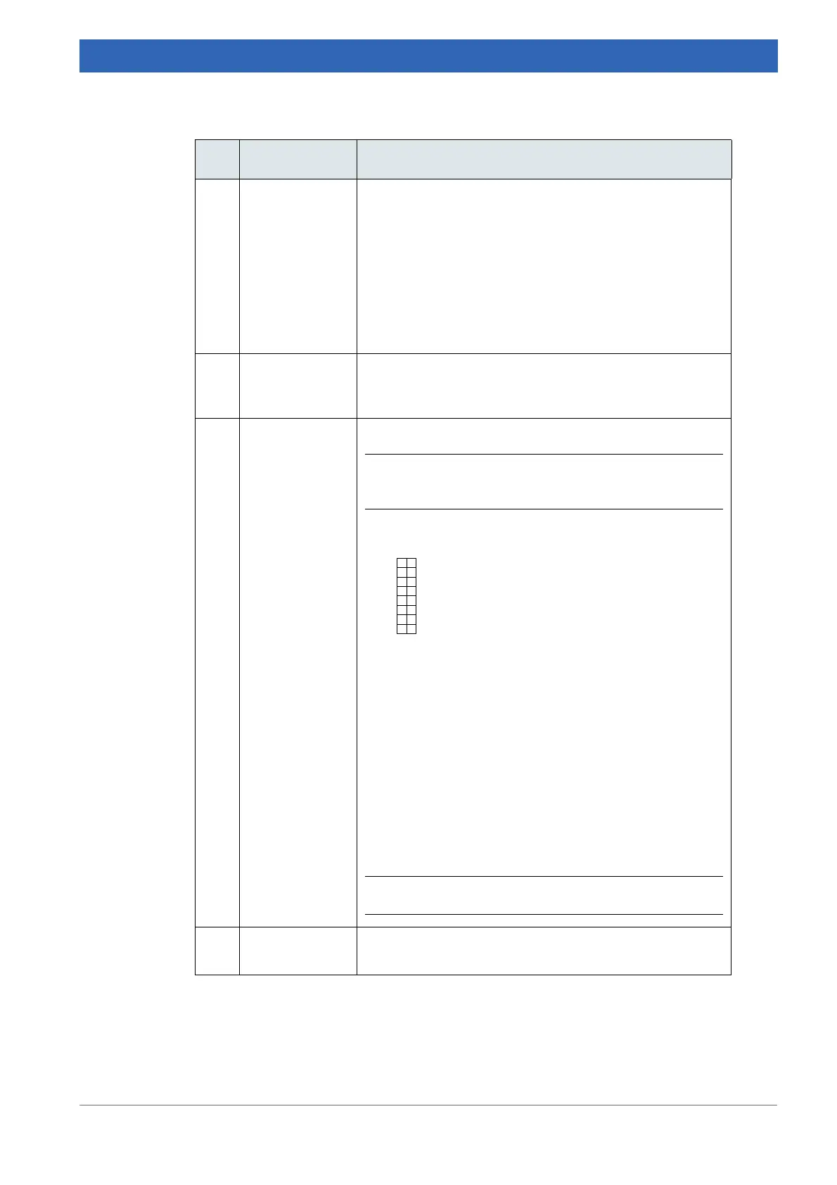
E TEST port The TEST port is intended for service and diagnostics.
i Do not connect any device to this port except for ser-
vice purposes!
Test receptacle:
Pin assignment:
1 LASA (Laser A)
2 AGND (Ground for 1 + 3)
3 LASB (Laser B)
4 FWDLSW
5 DGND
6 BWDLSW
7 LASXAF
8 DGND
9 SCM+ (Scanner Voice Coil)
10 SCM- (Scanner Voice Coil)
11 DCANA
12 - 16 Spare
i Do not short-circuit any pins!
F
RS232 port The R232 port is a spare serial interface port for future
use.
Component Definition
Table 10.2: Ports on flange panel
 Loading...


