4
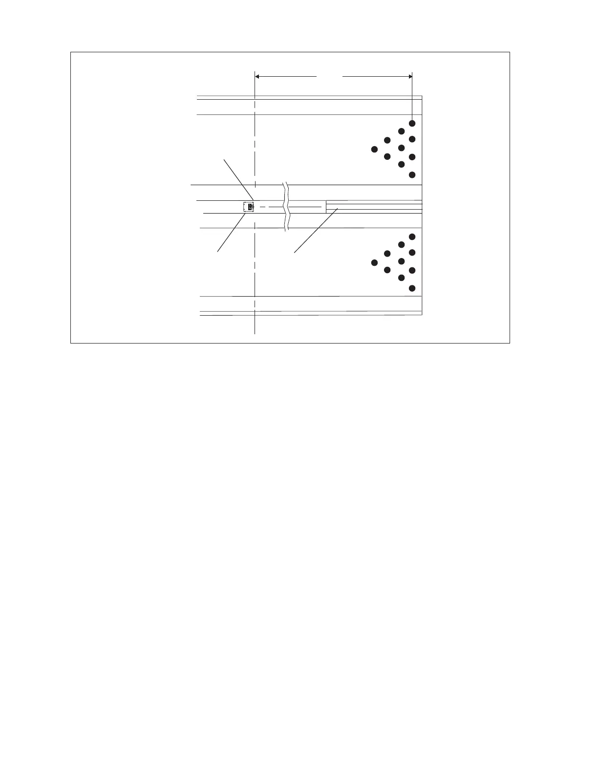
Sync Camera Assembly
L
C
(1)
FRONT EDGE OF
CHASSIS
(2)
BALL RETURN
CAPPING
150
(3.81 M)
(3)
CAMERA
ASSEMBLY
R1
C1
J3
L1
57-501318-000
OPEN
TP2
TP1
D2
+12V
GND
CAMERAINTERFACE
D1
1
J1
U1
R7
C3
+
C2
R2
R3
R4
R5
R6
J2
6
9
5
1
CAMERA
VIDEO OUT
+12V
L2
F1
R11
R8R9R10
SW1
4321
GAIN
D3
Camera Position
(1) FRONT EDGE OF CHASSIS (2) BALL RETURN CAPPING (3) CAMERA ASSEMBLY
The Sync camera consists of the following components:
Ball Detect - The ball detect is an infrared device that senses when a ball has been thrown. The signal
from the ball detect tells the system when to begin the scoring cycle for a lane.
Pinsetter Modications - A sweep (rake) switch is added to the pinsetter to make sure the camera
takes the picture at the proper time during the pinsetter cycle. Also connections into the pinsetters
circuits allows auto triggering of the pinsetter, special pinsetter cycles for No Tap or 3rd ball-10th frame
situations, and AMF short cycle.
Camera Assembly - The Camera Assembly contains the pin camera and the Camera Adapter Board. It
connects to the Peripheral Controller via a power cable and a video coax cable.