12 Troubleshooting
GS Pinsetters
Circuit Description:
Scoring for all GS-Series pinsetters is generated in the pinsetter’s electrical box.
Nexgen and later Consolidated electronics are connected directly to the Peripheral Controller through
an RS-485 cable. Earlier Consolidated electronics and Universal electronic systems connect to the
Peripheral Controller via an interface called a GS-controller. Typically, if scoring errors occur for a
GS-pinsetter, the problem is in the pinholder(s) of the machine, an adjustment to the setting table such
as the stroke limiter or table level, or switch cluster timing. Fail to score situations may be attributed to
the ball detector, the interface box (if used), the electronics of the machine, or to the Distribution PCB
inside the Peripheral Controller.
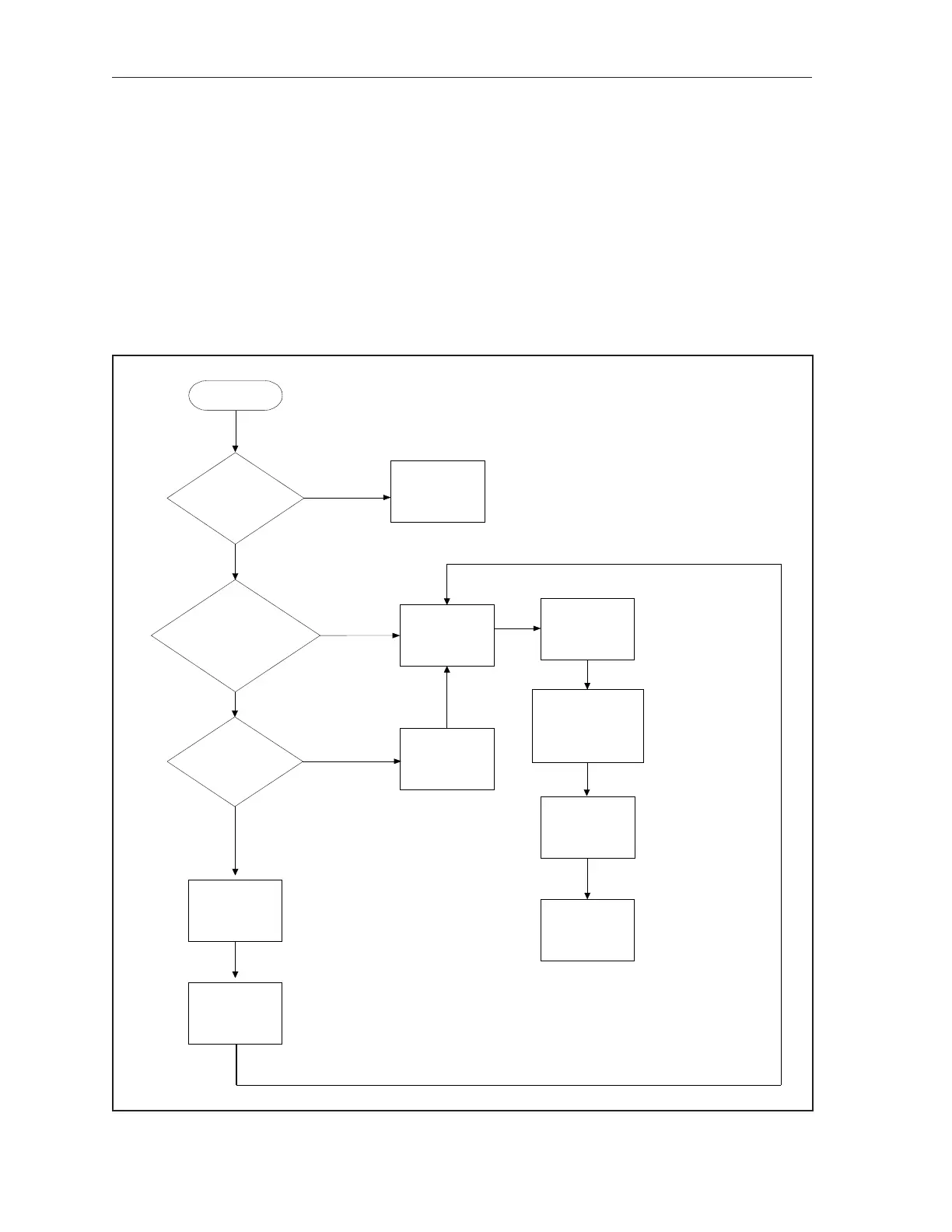
No Scoring on One Lane or Lane Pair (GS Pinsetters)
Start Here
Check the
wiring from the
transformer to
the
GS Controller
Check the Fuses
in the
GS
Controller’s power
transformer
Does the
installation have
aGS Controller
installed?
Does the GS
Controller
Have Power?
Cycle power to
the GS
Controller
Check the RS-485
Cable Between the
Peripheral Controller
and the Pinsetter
Cycle Power to
the Pinsetter
Electrical Box
Replace the CPU
PCB In the
Pinsetter
Electrical Box
NO
YES
YES
NO
Is the
pinsetter is
10-pin mode?
YES
NO
Put the pinsetter
into Frameworx
mode
Reset the
Distribution board
(Press white button)
Replace the
Peripheral
Controller