Sync Scorer Components 33
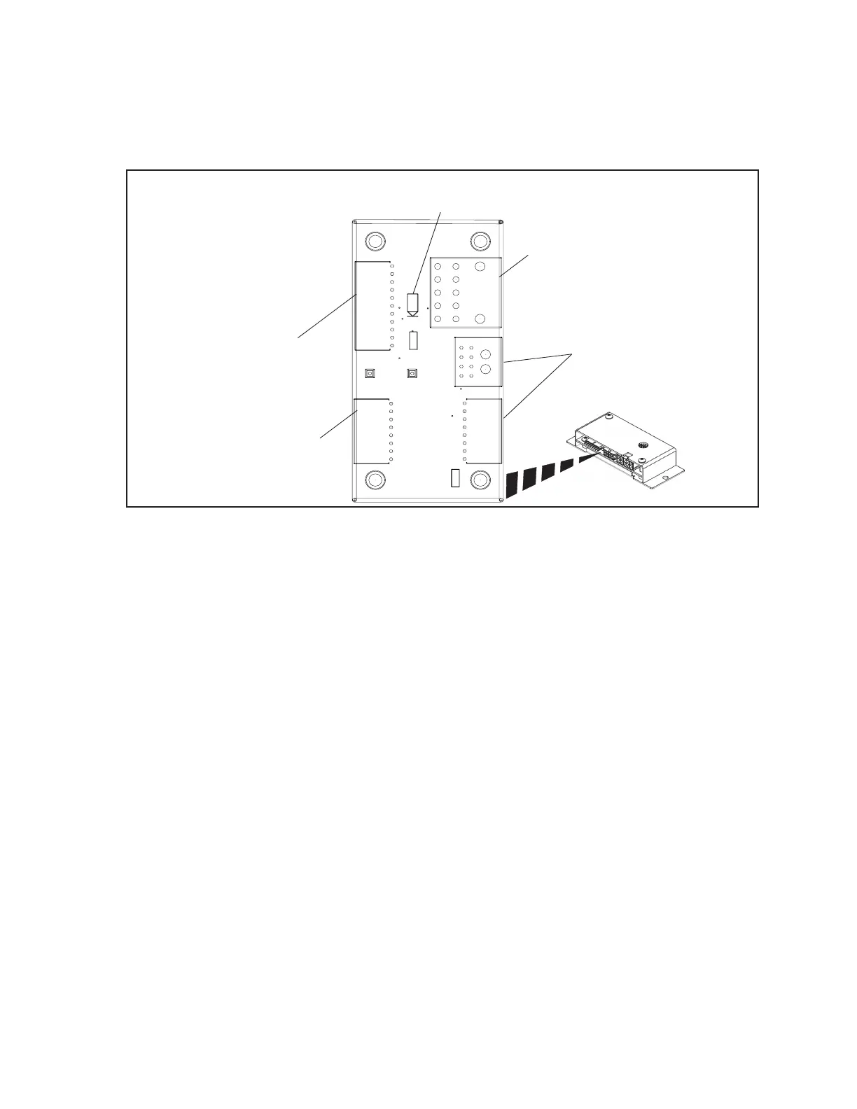
Touchpad Cable Interface PCB - Dual Pedestal Touchpads
To conveniently connect cables to a dual pedestal Touchpad as well as route the cables lane to lane, a
connection board called a Touchpad Cable Interface is used. The board is located under the lanes, near
the ball lift.
(4)
INTERCOM
AUDIO
OUT
(2)
COMMUNICATION /
POWER / EXICTER AUDIO
IN
(3)
INTERCOM
AUDIO
IN
(1)
POWER
LED
(5)
COMMUNICATION /
POWER / EXICTER AUDIO
OUT
R1
J1
J3
J2
J4
+12V
TP2
TP1
LAN_IN
AUDIO_IN
AUDIO_OUT
J5
D1
+12V
GND
L1
Cable Interface - Dual Pedestal Touchpads
The function of the components and connectors on the Cable Interface for dual pedestal touchpads are:
(1) Power LED (D1) - This LED turns “ON” when 12 VDC power is received at the board. Refer
to (2) Communication / Power / Exciter Audio In (J1).
(2) Communication /Power/Exciter Audio In (J1) - Connection for the power, communication
and audio exciter signals that originate at the Peripheral Controller. The signals that enter the
board at this connection pass through the board and directly connect to output connector J2.
This connection handles the signals for both lanes. Refer to (5) Communication/Power/Exciter
Audio Out (J2).
(3) Intercom Audio In (J3) - Input of the intercom audio(s) originating at the control desk Audio
Control box. If the board is located at the rst lane pair, the cable comes from the control desk
Audio Control box. For the reset of the lanes, the cable comes from the Cable Interface PCB for
the previous lane pair. Refer to (4) Intercom Audio Out (J4,J5).
(4) Intercom Audio Out (J4,J5) - Output connectors for the intercom audio that entered the board
at J3. The J5 connection allows the continuation of the intercom audio(s) to the Cable Interface
board for the next lane pair. Connection J4 connects the intercom audio to J5 on the Touchpad
Interface board inside the dual pedestal.
(5) Communication/Power/Exciter Audio Out (J2) - Output for the power, communication
and audio exciter signals that originated at the Peripheral Controller and entered the board at
connection J1. These signals are routed to J2 on the Touchpad Interface board inside the dual
pedestal. This connection handles the signals for both lanes. Refer to (2) Communication/
Power/Exciter Audio In (J1).