16
Sync Camera Assembly
CAMERA ASSEMBLIES
The camera assembly consists of a camera and Camera Adapter Board. The adapter board provides
the connections needed to power the camera and send the pin images from the camera to the Peripheral
Controller via a coaxial cable.
Centers upgrading from a Vector scoring system can use their Vector camera assemblies to supply
pin images to the Peripheral Controller. In these situations, the Distribution board is removed from
the camera inclosure and replaced by the Camera Adapter Board. Refer to the gure titled Camera
Adapter Board.
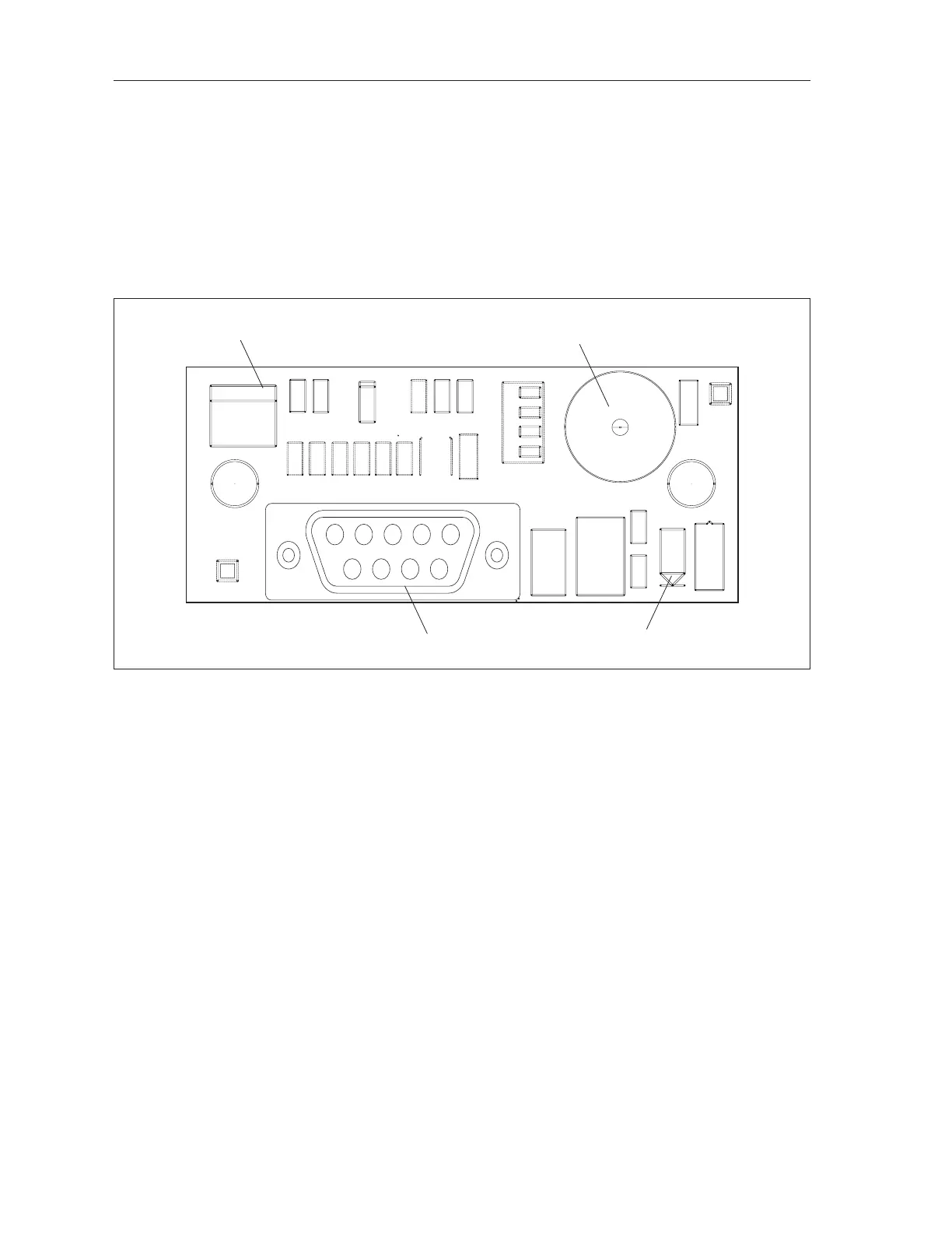
(4)
VIDEO
OUT
(3)
TO
CAMERA
(1)
POWER
IN
(2)
POWER
LED
R1
C1
J3
L1
57-501318-000
OPEN
TP2
TP1
D2
+12V
GND
CAMERA INTERFACE
D1
1
J1
U1
R7
C3
+
C2
R2
R3
R4
R5
R6
J2
6
9
5
1
CAMERA
VIDEO OUT
+12V
L2
F1
R11
R8 R9 R10
SW1
4321
GAIN
D3
Camera Adapter Board
The function of the connections on the Camera Adapter Board are:
(1) Power In - (J3) RS232 serial port that provides power used by the board and the camera.
(2) Power LED - (D2) This LED illuminates to indicate the board has power.
(3) To Camera - (J1) Connection to the camera. This connection provides power to the camera
and receives video from the camera.
(4) Video Out - (J2) Connection used to send the camera video to the Peripheral Controller.