40 Sync Scorer Components
DISPLAY CONTROLLER
Connections
The Display Controller receives scoring information from the Peripheral Controller through a network
connection. Using this information it provides the high denition scorer video to the monitor for a lane
pair using HDMI cables. It also can provide on/off and video input control for the monitors thorough
serial ports (Com1, Com2, Com3). Refer to the gure titled Display Controller.
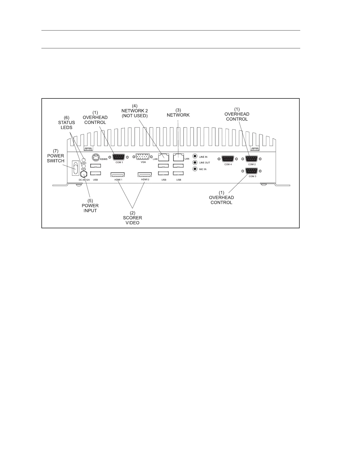
Display Controller
The function of the connections on the Display Controller are:
(1) Overhead Control - (Com 1, Com 2, Com 3) RS232 serial ports that provide On/Off and video
input control for the overheads.
(2) Scorer Video - (HDMI 1 / HDMI 2) HD Output connection to the LCD monitor for the scorer
video.
HDMI 1 - Left (odd) lane video.
HDMI 2 - Right (even) lane video.
(3) Network - (LAN) Connection for the ethernet network. The Display Controller communicates
with the other devices in the system through this connection.
(4) Network 2 (Not Used) - Disabled network port. Do NOT USE.
(5) Power In - (DC In 12v) Input for power coming from the power supply unit located behind the
left lane overhead monitor.
(6) Status LEDs - (HDD/SYS) The HDD LED ashes to indicate when the hard drive inside the
Display Controller is being accessed. The system LED lights when the Display Controller is
“ON”
(7) Power Switch - This switch turns the Display Controller ON/OFF.