20 Sync Control System
Audio Control Unit
The audio control unit is responsible for interfacing the intercom audio to the scoring system. Refer to
the gure titled Audio Control Unit - External View.
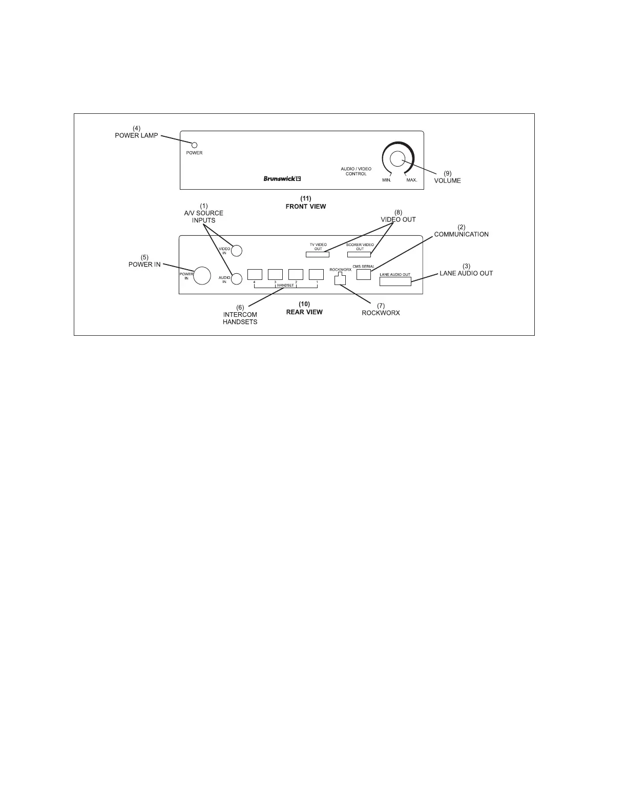
Audio Control Unit - External View
(1) A/V SOURCE INPUTS (2) COMMUNICATION (3) LANE AUDIO OUT
(4) POWER LAMP (5) POWER IN (6) INTERCOM HANDSETS
(7) ROCKWORX (8) VIDEO OUT (9) VOLUME
(10) REAR VIEW (11) FRONT VIEW
The function of the connectors on the audio control unit are:
(1) A/V Source Inputs - Not used
(2) Communications - Connection for the communication coming from the Sync computer.
(3) Lane Audio Out - Output connector for the “global audio” cable that delivers the intercom
audios to the Sync Touchpads or Vector keypads.
(4) Power Lamp - The light is on whenever power is supplied to the box.
(5) Power In - Main power input to the box. The input to the box is 5 VDC, 12 VDC and -12 VDC.
(6) Intercom Handsets - Connection for the cable(s) coming from the intercom handset/switch
box(es). Two handsets can be attached to the AV box. Do not use inputs 3 or 4.
(7) Rockworx - Not used.
(8) Video Out (2) - Not used.
(9) Volume- Not used.