52 Sync Scorer Components
Selecting Input Voltage for Auxiliary or Secondary Transformers
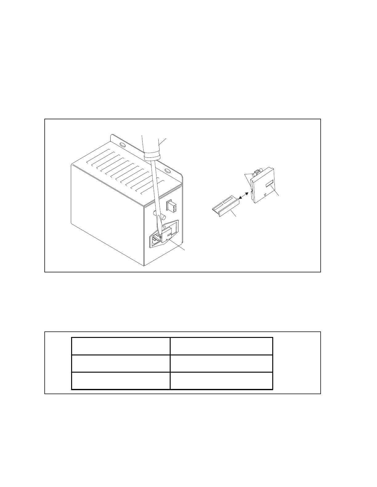
1. Disconnect the power cord from the HDLC Power Supply.
2. Using a at head screwdriver, remove the fuse holder from the power receptacle. Refer to gure
titled Selecting Input Voltage for HDLC Power Supply.
3. Remove the Voltage Selector PCB from the holder assembly.
4. Insert the Voltage Selector PCB so the desired voltage rating can be seen through the opening in
the holder. Refer to the gure titled Selecting Input Voltage for HDLC Power Supply.
(1)
REMOVE FUSE HOLDER
FROM POWER
RECEPTACLE
(2)
FLAT HEAD
SCREWDRIVER
(3)
VOLTAGE SELECTOR
PCB
(4)
OPENING IN
HOLDER
(5)
FUSES
220-240V
110-120V
110-120
Selecting Input Voltage for HDLC Power Supply
(1) REMOVE FUSE HOLDER (2) FLAT HEAD SCREWDRIVER (3) VOLTAGE SELECTOR PCB
FROM POWER RECEPTACLE
(4) OPENING IN HOLDER (5) FUSES
5. Examine the fuses in the holder to verify the proper fuse rating according to the charts below:
Input Voltage Fuse Ratings
110 VAC - 120 VAC 2 AMP 250V
220 VAC - 240 VAC 1 AMP 250V
6. Replace the fuse holder in the power receptacle.
7. Connect the power cord to the HDLC Power Supply.