Sync Control System 19
Intercom Handset/Switch Box
The intercom handset/switch box allows an intercom handset to connect to the scoring systems. The
box connects to the audio/video unit through an intercom beeper assembly and provides a telephone
style intercom handset that allows the operator to have a two-way conversation with a bowler standing
at a scorer console. Up to two boxes can be connected to the Audio Control unit.
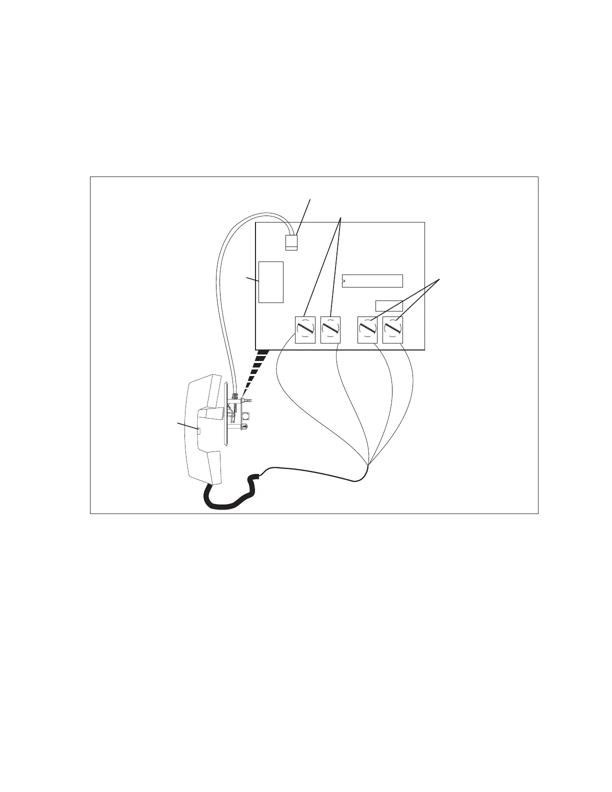
Inside each handset/switch box is a circuit board that handles all the functions for the intercom. This
board is called the Handset Interface PCB. Refer to the gure titled Handset Interface PCB.
(3)
HANDSET
MICROPHONE
BLK
RED
WHT
WHT
(4)
HANDSET
SPEAKER
(1)
AUDIO
IN/OUT
(5)
HANDSET
SPEAKER
VOLUME
(2)
HOOK
SWITCH
J1
J2
Handset Interface PCB
The function of the components on the Handset Interface PCB are:
(1) Audio In/Out (J1) - Telephone type connector (RJ-11) used to connect the box to the audio/
video unit. This allows the transfer of the “audio” to and from the scoring systems.
(2) Hook Switch (J2) - Connection to the hook switch located in the box. The switch allows the
operator to connect to the console simply by lifting the handset. Replacing the handset on the
“hook” disconnects the intercom.
(3) Handset Microphone - Connection to the microphone in the mouthpiece of the handset.
(4) Handset Speaker - Connection to the speaker in the earpiece of the handset.
(5) Volume Control - The volume control allows the control desk operator to adjust the audio level
of the earpiece of the handset.