22 Sync Control System
CMS Audio PCB
The CMS Audio PCB is responsible for interfacing the up to two intercom handsets to the scoring
system. The audio (global audio) is amplied by the PCB prior to being sent out to each scorer console.
The PCB interfaces the intercom audios to the system by allowing simultaneous conversation between
the Control Desk and two consoles. In addition, the PCB allows the bowler and the control desk to talk
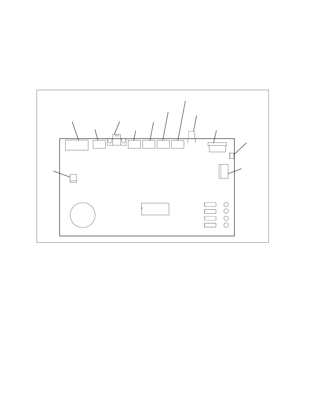
at the same time, eliminating the need to press a button to talk or listen. Refer to the gure titled CMS
Audio PCB.
(1)
AUDIO INPUT
(12)
VOLUME
(8)
POWER IN
(10)
POWER OUT
(3)
CMS SERIAL
(9)
POWER
LAMP
(4)
HANDSET 1
(5)
HANDSET 2
(6)
HANDSET 3
(7)
HANDSET 4
(11)
ROCKWORX
(2)
AUDIO
OUTPUT
J5
J12
J11
J8
J10
J7
J6 J1
J9
J2 J3 J4
CMS Audio PCB
The functions of the components and connections on the Audio PCB are as follows:
(1) Audio Input (J7) - Not Used
(2) Audio Output (J5) - Connection for the intercom audio being sent to the Sync Touchpads or
Vector keypads for each lane. (Referred to as Lane Audio on the back of the unit).
(3) CMS Serial (J6) - Connection for the communication coming from a Sync computer. This
communication allows the computer to determine which intercom handset has been used
to answer an intercom request. Communication is then sent to the scorer computer of the
requesting lane so that the proper intercom line is selected.
(4) Handset 1 (J1) - Connection for cable coming from the intercom handset/switch box for the
rst handset.
(5) Handset 2 (J2) - Connection for cable coming from the intercom handset/switch box for a
second handset.