26 Sync Scorer Components
Sync Interface - Single Pedestal / Table Mount Tablet
The interface board for single pedestal or table mounted tablets connects the tablet to the internal
speakers and microphone and provides 12VDC to power the tablet. Refer to the gures titled Sync
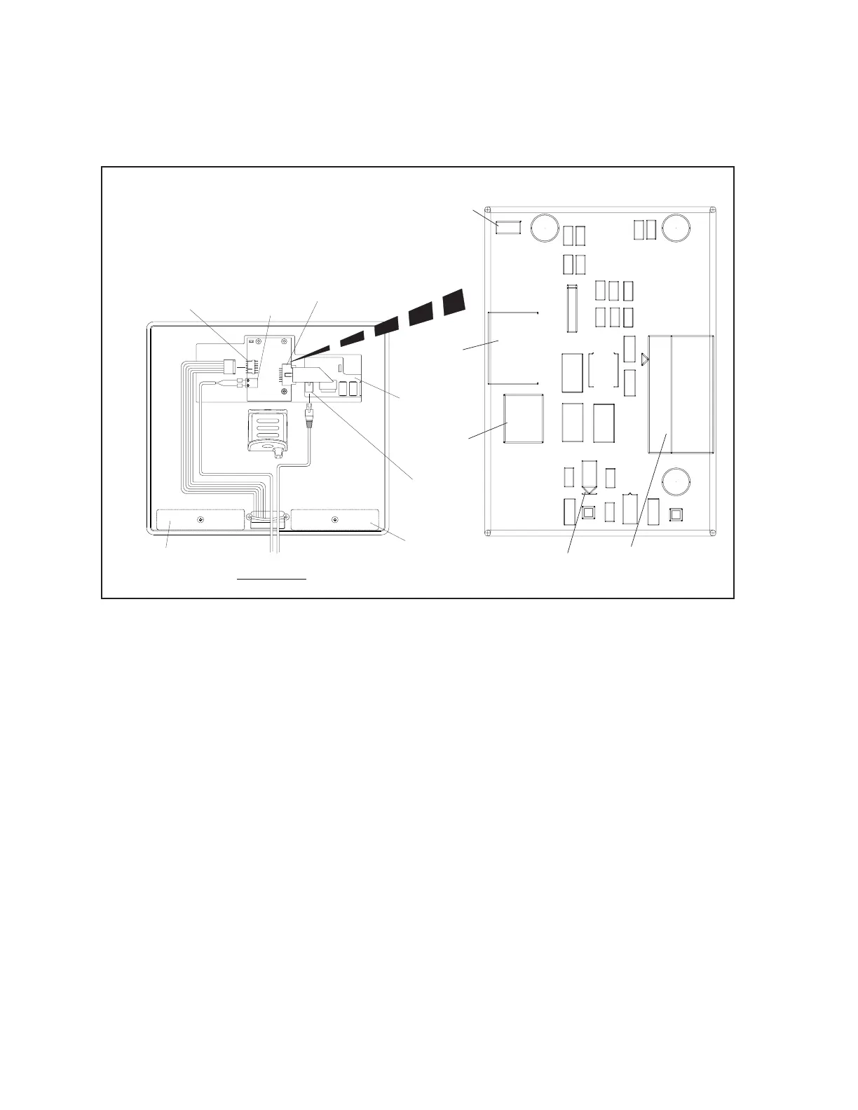
Interface - Table / Single Pedestal.
J1
RED
BLACK
+
-
VIEW FROM BACK
-
+
(1)
J4
TO
TOUCHSCREEN
(2)
J3
POWER
INPUT
(5)
D1
POWER
LED
(6)
JPR1
SPEAKER
CONFIGURATION
JUMPER
(2)
J3
POWER
INPUT
(1)
J4
TO
TOUCHSCREEN
(3)
ETHERNET
CONNECTION
(4)
J1
TO
SPEAKERS /
MICROPHONE
(4)
J1
TO
SPEAKERS
MICROPHONE
J4
L10
R1
C6C5
C2
C1
L6
J1
D5
D3
U1
JPR1
1
J3
2
57-501295-000
+12V
BRUNSWICK BP
TP1
TP3
L3
J4
C9
C3
L1
L2
L8
L9
INTERFACE TM
SP_G
C4
RS-232
POWER IN
+
D4
-
D2
SP & MIC
C7
D1
+12V
GND
L5
L7
C8
L4
(8)
SPEAKER
(8)
SPEAKER
(7)
TABLET
PCB
Sync Interface - Single Pedestal / Table Mounted Tablets (Non Upgrade Version)
The function of the components and connectors on the table/single pedestal mounted Sync Interface are:
1) To Touchscreen - (J4) Connection to the tablet for the speaker and microphone signals and
12VDC power.
(2) Power Input - (J3) Input for 12 VDC originating at the Sync console power supply located on
the curtain wall.
(3) Ethernet Connection - Connection for the Cat5e cabling from the Sync system network.
The Sync tablet communicates with the control system, Display Controllers, and Peripheral
Controller box through this connection.
(4) Speakers / Microphone - (J1) Connection for the speakers and micophones located in the
console.
(5) Power Led - (D1) This LED turns “ON” when 12 VDC power is received at the board. Refer to
(2) Power Input.
(6) SpeakerCongurationJumpers - (JPR1) Jumper used to select the grounding method of the
speakers.
JPR1 - Ground Method. Remove Jumper (Default)