Sync Camera Assembly
3
GENERAL DESCRIPTION
The Sync camera assembly is an electrical/optical device used with non-GS series pinsetters to count
standing pins, control on/off and machine reset for a pair of pinsetters, and interface the foul units to the
scoring system. The system uses a camera, ball detect assemblies, and special pinsetter modications
to accomplish this. These components connect to the Peripheral Controller which uses the signals to
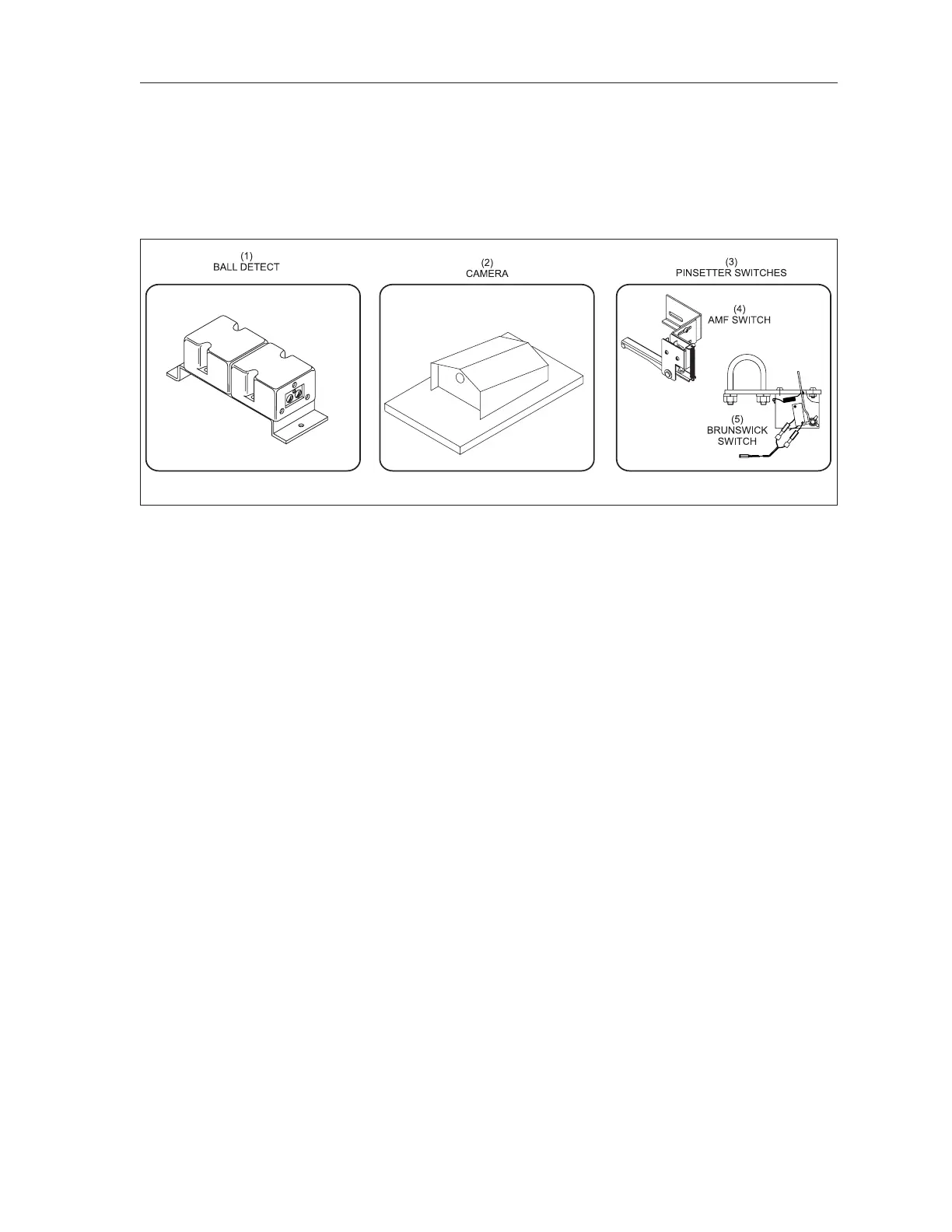
determine pincount. Refer to gure titled Sync Camera Scoring Components.
Sync Components
(1) BALL DETECT (2) SYNC CAMERA (3) PINSETTER SWITCHES
(4) AMF SWITCH (5) BRUNSWICK SWITCH
The Sync camera chassis is mounted on the ball return capping of a lane pair so that the front edge of
the unit is approximately 150” (3.81 m) from the center of the last row of pins. Refer to gure titled
Camera Position. The assembly uses a single camera to take a picture of the pit area of both pinsetters.
The picture is sent by the Camera Adapter Board to the Peripheral Controller where it is analyzed.
During the analysis, a portion of the picture is searched for bright reections and shapes resembling
pins. This is compared to a stored calibration to determine if the reection level for the pins is above a
reference brightness level set by the user through the control desk. Any reection level that is above the
set level is counted as a standing pin.
An infrared ball detect is mounted near the pinsetter and a switch is mounted on the pinsetter to
monitor the rake (sweep) drop are used to ensure that the unit scores only after a ball has been thrown
and the pinsetter has triggered. (A ball detect signal will not be accepted unless the switch is actuated.)
Scoring occurs after a the rake (sweep) switch contacts have closed and a user determined time delay
has passed. In the event that the pinsetter does not cycle on its own, the system will score then cycle
the pinsetter using the machines reset circuit.
Centers upgrading from a Vector scoring system can use their Vector camera and related components
to supply pin images to the Peripheral Controller. In these situations, the Distribution board is removed
from the camera inclosure and replaced by the Camera Adapter Board.