Sync Camera Assembly
15
NPS Switch
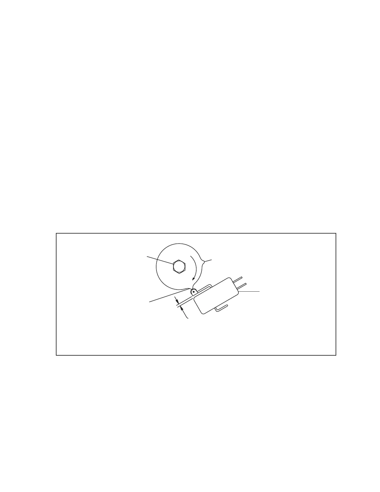
To adjust the NPS switch, perform the following steps. Refer to the gure titled NPS Switch
Adjustment.
1. Cycle the pinsetter to a full rack rst ball.
2. Lower the pinsetter deck until it is approximately 15” above the pindeck (at standing pin height).
3. Loosen the lockscrew holding to outer cam to the shaft.
4. Rotate the outer cam clockwise until the roller of the switch lever is positioned halfway up the
front edge of the outer cam.
5. Tighten the cam lockscrew.
6. Cycle the pinsetter so that the switch is at the top of the lobe.
7. Loosen the NPS switch mounting screws.
8. Adjust the switch so that it activates and there is approximately .025” gap between the switch
and the switch lever to prevent switch damage.
9. Tighten the switch mounting screws.
(2)
SECOND LOBE
(5)
NPS SWITCH
(4)
.025"
OVERTRAVEL
AT TOP OF
LOBE
(3)
ACTUATE HALFWAY
UP FIRST LOBE
(1)
LOCKSCREW
NPS Switch Adjustment
(1) LOCKSCREW (2) SECOND LOBE (3) ACTUATE HALFWAY UP FIRST LOBE
(4) .025” OVERTRAVEL AT TOP (5) NPS SWITCH
OF LOBE