14
Sync Camera Assembly
Switch Cluster Adjustments
The Switch Cluster contains three switches. Two of these switches, the 0
o
and the NPS switch are used
with the Sync scoring system to provide timing for the New Pins Solenoid. The third switch was used
only for timing of the ball director on the Systems 2000 Ball Rack.
Correct adjustment of the NPS
switch is necessary to ensure the solenoid does not energize too late into
the pinsetter cycle while proper adjustment of the 0
o
ensures that the pinsetter will switch to second ball
at the end of the pinsetter cycle. Both switch adjustments should be checked after clutch adjustment,
detector repair, or any other change to the timing of the pinsetter.
0
o
Switch
The lobe of the inside cam on the Switch Cluster must actuate the 0
o
switch when the pinsetter
completes its cycle and is at 0
o
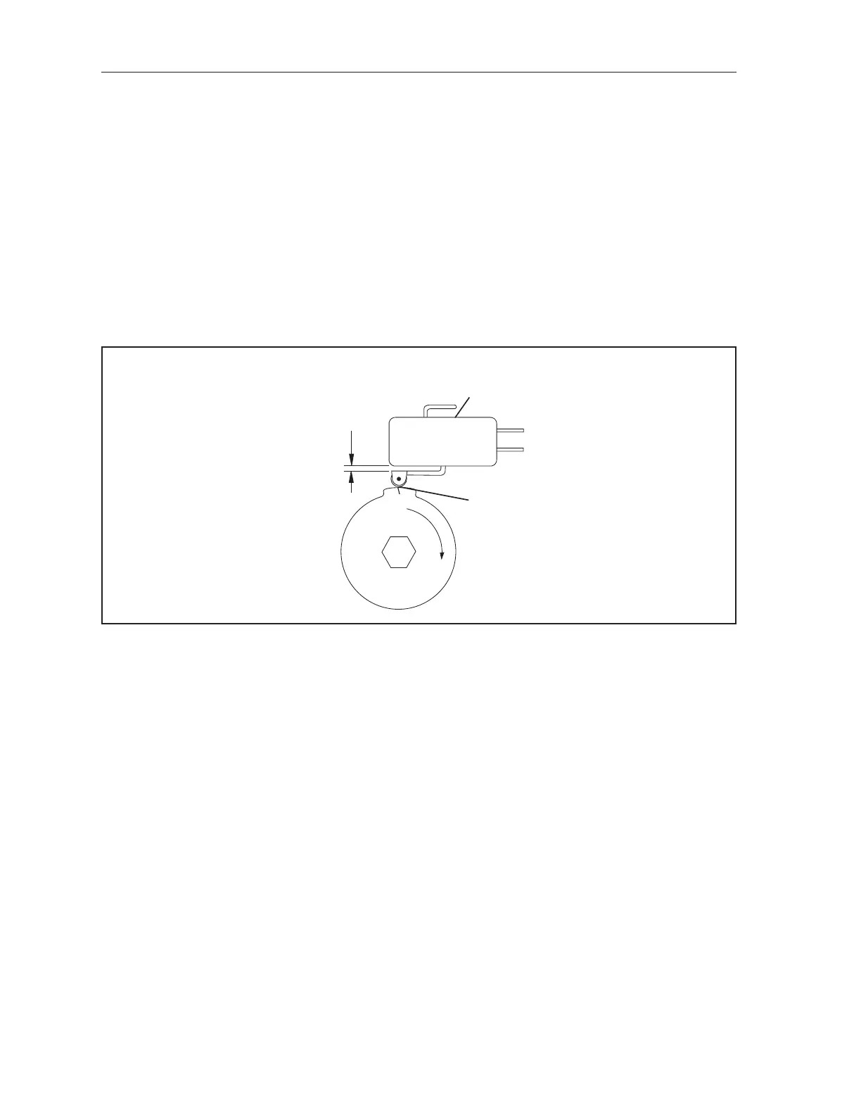
. Refer to the gure titled 0° Switch Adjustment.
(1)
.025"
OVERTRAVEL
AT TOPOF
LOBE
(2)
0º SWITCH
(3)
MARK
ON LOBE
0° Switch Adjustment
(1) .025” OVERTRAVEL AT TOP (2) 0º SWITCH (3) MARK ON LOBE
OF LOBE
Adjusting the 0
o
cam is done by removing the Switch Cluster Assembly from the detector’s 1:1 gear
and repositioning the cam to actuate the 0
o
switch. (The pinsetter must be at 0
o
.) To adjust the switch
perform the following steps:
1. Remove the switch cluster from the detector.
2. Position the cam and switch so the switch is activated at the scribe mark located near the middle
of the lob. Reference the gure titled 0° Switch Adjustment. An overtravel dimension of .025”
is necessary at the top of the lobe to prevent damage to the switch.
3. Replace the cluster on the detector making sure that the cam does not change position.