38 Sync Scorer Components
Keypad Interface PCB
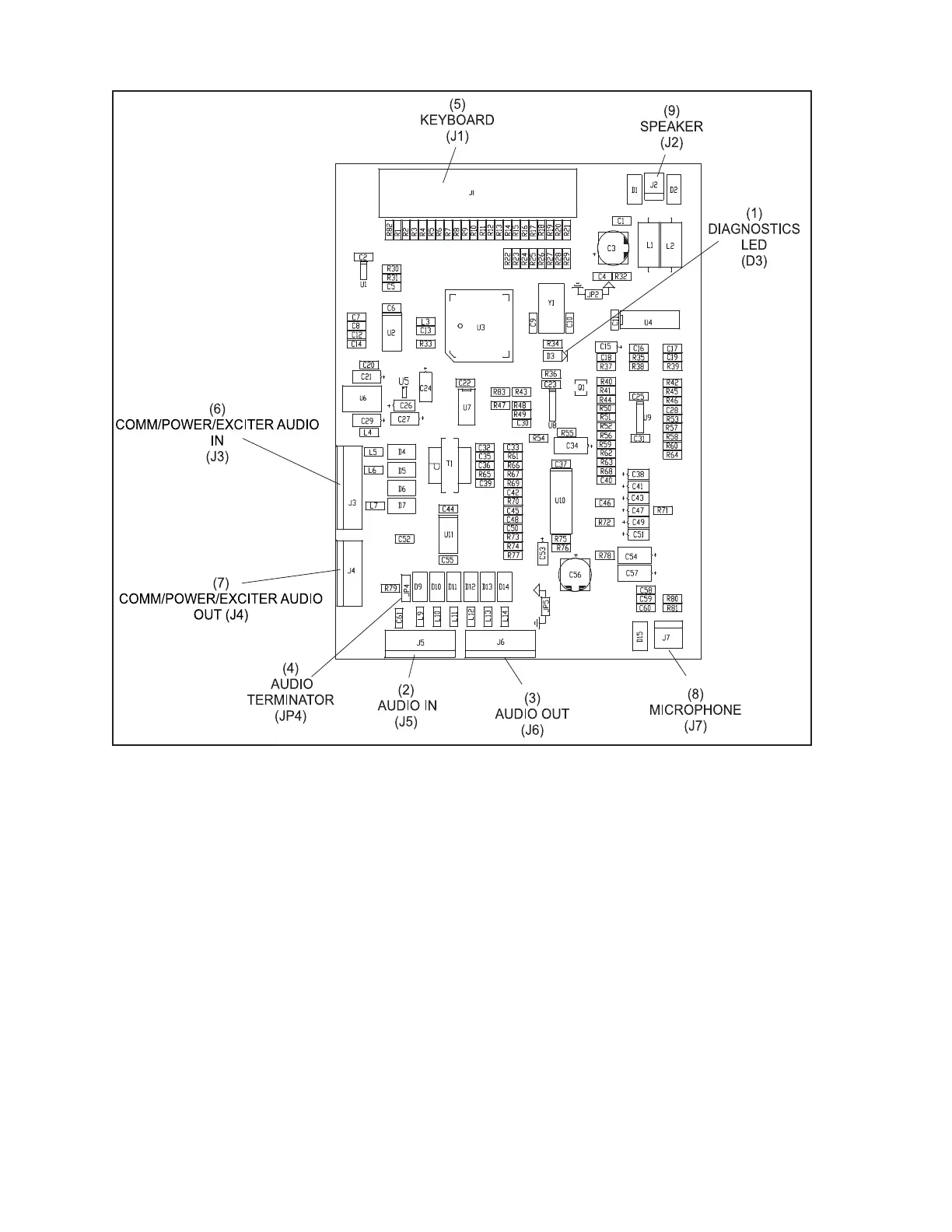
The function of the connectors and components on the Keypad Interface are:
(1) Diagnostic LED (D3) - This light ashes to indicate that the PCB is functioning.
(2) Audio In (J5) - Input of the intercom audio(s) originating at the control desk Audio Control
box. If the board is located in the rst console, the cable comes from the control desk Audio
Control box. For the reset of the lanes, the cable comes from the Keypad Interface PCB for the
previous lane. Refer to (3) Audio Out (J6).
(3) Audio Out (J6) - Output of the intercom audio for the next console. This connection allows the
continuation of the intercom audio(s) to the next lane. If the board is installed in the last console
and the signals do not continue, they are terminated using the termination jumper JP4. Refer to
(4) Audio Terminator (JP4).
(4) Audio Terminator (JP4) - Jumper used to terminate the intercom audio signal. If the intercom
audio cable does not continue to another console from J6, terminate the signal by placing a
jumper between pins 2 and 3 (T). Otherwise place a jumper between pins 1 and 2 (U).