50 Sync Scorer Components
The functions of the connections on the HDLC Interface Board are:
(1) 28 VAC Power In (J3) - Input for the voltage originating at the HDLC Power Supply located on
the curtain wall, next to the Interface Box.
(2) 28 VAC Power Out (J4) - Output for the voltage going to the step-down transformer located
inside the Interface Box.
(3) 9.5 VAC Power In (J5) - Input for the voltage returning for the step down transformer. This
voltage is then changed to +5 VDC on the board.
(4) J2 To Pinsetter (J2) - Connection for communication to P1 connection of the Gamesetter Box
on GS-10, GS-92 or GS-96 or P8 on the Consolidated Low Voltage Box of GS-98 pinsetters.
Information handled by this communication includes pinsetter on/off, frame count monitoring,
scores, and special cycle information.
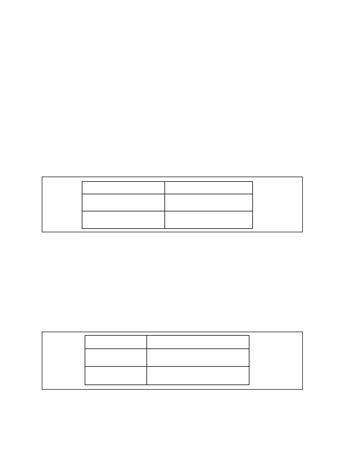
(5) Termination Jumper (J8) - Jumper used to terminate the communication signal coming from
the Peripheral Controller if it does not continue to additional devices. Set the jumper as follows:
Configuration Jumper Placement
No additional devices connected
to J7 (Terminated)
Short Pins 1 and 2 (T)
Additional devices connected to
J7 (Not terminated)
Short Pins 2 and 3 (U)
(6) Peripheral Communication Out (J7) - Connection to allow the communication signal from
the Peripheral Controller to route to additional devices on a lane pair. Currently this connection
is not used. . Refer to (5) Termination Jumper (J8).
(7) To Peripheral Controller (J6) - Connection for the communication signal coming from the
Peripheral Controller. All information needed by the Interface to control the machine and
obtain scoring information, are handled through this cable.
(8) Heartbeat LED - The Heartbeat LED allows the user to monitor the communication between
the board and the pinsetter. The LED can have the following ash rates. Refer to (4) J2 To
Pinsetter.
Flash Rate Meaning
Flash, Flash, Pause Normal Communication to Gamesetter
Fast Flashing No Communication to Gamesetter