3
FI002K0018v1100UK – THS/21 Instruction manual for installation, use and maintenance
INSTALLATION
110 ORIGINAL INSTRUCTIONS
3.8.9.6 Automatic ejection with photocell synchronization (EM=FS)
EM
Typical product Ejector Type Ejection Notes
FS
Single-line, light, poorly
spaced packed product.
Very high throughput.
Air jet
Contaminated product
automatically ejected
Synchronization photocell
required
Operation with automatic ejection of contaminated material, synchronized by photocell. Very similar
to the previous application, this mode can be used for packaged products, for applications at
speeds greater than 60 m/min.
The synchronizing photocell must be installed at the antenna exit only.
In this case, the response times of the photocell, the Metal Detector and the ejector cannot be
ignored. We would generally advise users to check operation of the ejector through trial and error,
changing its position and adjusting parameter ED.
Programming menu
Remote
parameter
Description Setting
Ejection > ejection mode
EM
Automatic removal of contaminated material
with synchronization on the removing area
FS
Ejection > ejector
ED
Distance of ejector from the centre of the probe
0 - 6000 mm
Ejection > pack length
PLEN
Nominal length of pack
20 - 250 mm
Ejection > eject.sync.start
ES
Synchronizing zone for the start of ejection
0 - 250 mm
Ejection > eject.sync.end
EE
Synchronizing zone for the end of ejection
0 - 250 mm
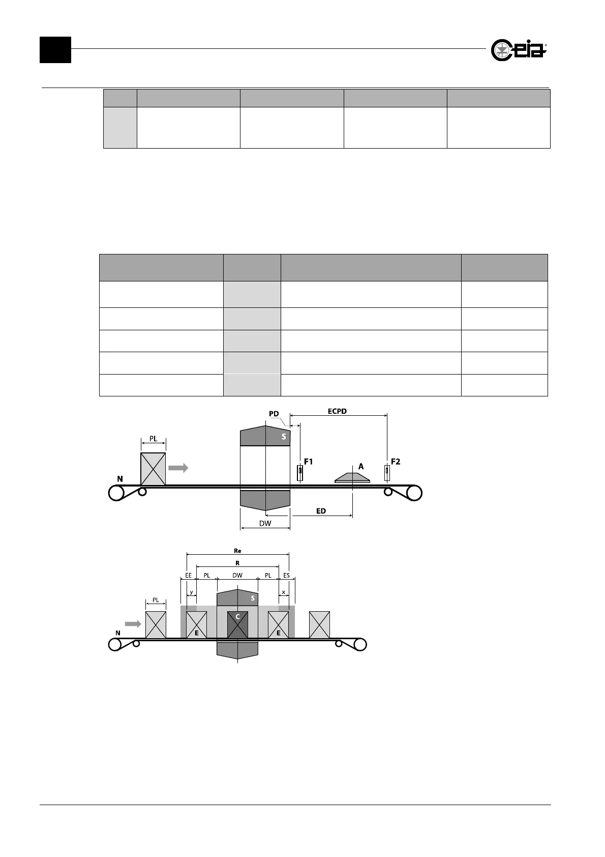
S: Metal Detector probe
N: Conveyor belt
A: Air jet ejector
F1: Synchronization
photocell
F2: Ejection check sensor
PL: Pack length
DW: Detector width
ED: Ejection distance
PD: Photocell distance
ECPD: Photocell distance
E: Ejected pack;
C: Contaminated and ejected pack;
EE: Ejection end synchronization area;
ES: Ejection start synchronization area
R: Minimum removal area
Re: Actual removal area = R+x+y
Following an alarm, the ejector will be activated for the time of the alarm and to eject all products in
the PL+DW+PL area.
A control can be introduced, from the photocell, of two areas alongside the removal area, in order
to synchronize the start and end of the ejection with the packs in transit (ES and EE respectively).
For more accurate adjustment of the ejection cycle, the early and delayed activation times can be
adjusted based on the actual activation and deactivation times, respectively, using ERT and ERF.