FI002K0018v1100UK – THS/21 Instruction manual for installation, use and maintenance
3
INSTALLATION
ORIGINAL INSTRUCTIONS 55
Applications at high speed (belt speeds greater than 60 m/min) (EM=FS)
In this case, the response times of the photocell, the Metal Detector and the ejector cannot be
ignored. We would generally advise users to check operation of the ejector through trial and error,
changing its position and adjusting parameter ED.
3.1.3 Installation guidelines for correct environmental compatibility of the Metal Detector
Possible sources of electrical interference may be power supply cables (electromagnetic fields
generated by alternating currents) or pulsing electromagnetic sources (electrical motors with
high start-up power absorption and their power supply cables, fluorescent lights, emergency
generators, remote control devices, etc.) located near the probe.
3.1.3.1 Power supply and control cables of other devices.
- Use sheathed power supply cables or interweave the conductors with the shortest possible
spacing.
- Keep the power cables as far as possible from the Metal Detector; otherwise, it is advisable
to put them in a metal conduit connected to earth on one side only and appropriately
fastened to prevent vibrations.
- Do not connect in any way power supply cables of other devices inside the Metal Detector
power supply box.
- Where possible, move the power cables away from cables of devices connected as inputs to
the Metal Detector (e.g. encoder) or screen them with a metal conduit connected to earth on
one side only.
3.1.3.2 Pulsed-type sources
- Move as far away as possible from the Metal Detector devices which might generate pulsed-
type disturbances, e.g. motors, inverters, electricity supply boards, electromagnetic actuators
(they should be replaced with similar pneumatic devices), fluorescent lights and related
starters (where possible, replace them with a filament bulbs).
- Provide electric motors with mains filters and
keep a minimum distance between the Metal
Detector and the motor, as indicated in the
table
based on the power of the motor.
Where possible, AC motors should be used
rather than DC motors.
- If they are installed near the Metal Detector,
the motors should be screened with
cylindrical steel (non-welded) enclosures no
less than 2 mm thick.
- Provide the electromagnets, remote control
switches and DC motors with dampening
circuits and interweave the relative power
supply cables with the shortest possible
spacing.
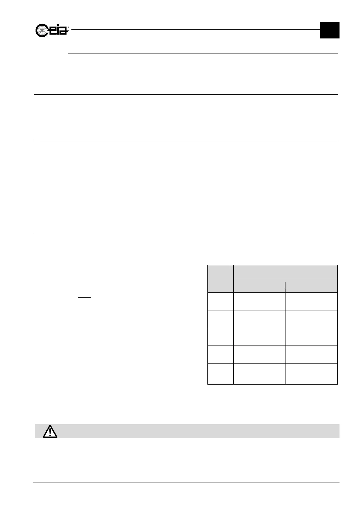
Power
(CV)
Minimum distance
THS/MN21 Other THS models
0,5
5 x DH
3 x DH
1
6 x DH
4 x DH
2
8 x DH
5 x DH
3
10 x DH
6 x DH
20
15 x DH
(10 x DH if screened)
10 x DH
(6 x DH if screened)
- Provide each inverter with filters or inductors at their infeed, selected based on the inverter
specifications.
- Provide the connection cable to the motor with a ferrite to be placed near the inverter,
passing one or more coils of the phase conductors through the ferrite itself.
Fix the probe cable to the power supply unit so that it cannot oscillate or vibrate.
If the cable is too long, DO NOT CUT THE CABLE: COIL UP THE EXCESS.