3
FI002K0018v1100UK – THS/21 Instruction manual for installation, use and maintenance
INSTALLATION
54 ORIGINAL INSTRUCTIONS
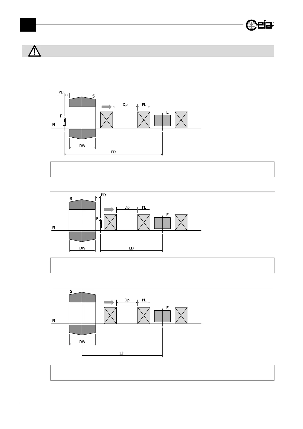
3.1.2.3.6 Ejection area
If an ejector with moving metal parts is installed in the ejection area, the distance from the antenna must comply with the
instructions in paragraph 3.1.2.2.
The position of the ejection area E, located at the probe exit, is constrained by the following
conditions:
Synchronization with photocell at the entrance to the probe (EM=S/SB)
N: conveyor belt;
S: electronics unit;
F: photocell;
PL: length of package;
E: ejection area;
DW: length of probe;
ED: distance photocell-ejector
(6m max);
Dp: distance between packs.
PD + DW + PL < ED < 62 x ( PL + Dp )
Synchronization with photocell at the exit from the probe (EM=S/SB)
N: conveyor belt;
S: electronics unit;
F: photocell;
PL: length of package;
E: ejection area;
DW: length of probe;
ED: distance photocell-ejector
(6m max);
Dp: distance between packs.
PL < ED < 62 x ( PL + Dp )
Without synchronization photocell (EM=F/B)
N: conveyor belt;
S: electronics unit;
PL: length of package;
E: ejection area;
DW: length of probe;
ED: distance probe-ejector;
Dp: distance between packs.
0.5 x DW + PL < ED < 6m