3
FI002K0018v1100UK – THS/21 Instruction manual for installation, use and maintenance
INSTALLATION
98 ORIGINAL INSTRUCTIONS
3.7.3.1 Sensor positioning
Sensor configuration and positioning depend on the application.
This section provides some examples which are intended as a guide only.
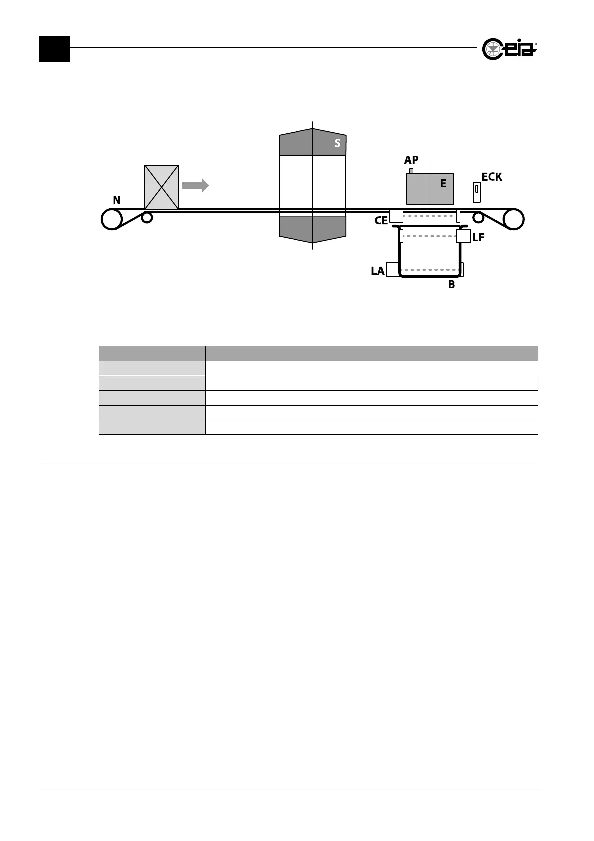
N: Conveyor belt; S: Metal Detector antenna; E: Ejection system;
B: Reject bin; AP: Air pressure sensor;
CE: Product ejection confirmation sensor; ECK: Product ejection check sensor;
LF: Reject bin full sensor; LA: Bin present sensor;
Input Description
EJECT. CONFIRMATION Check for ejection confirmation
EJECTION CHECK Check for complete ejection of product
LOW PRESSURE Check for compressed air pressure
BIN FULL Check for bin full
BIN ABSENT Check for bin presence
3.7.4 Connection of an ejector
The ejector should be connected according to its type and to the power supply box model:
- single solenoid *: use the EJECT relay (J02 on 00211ALM board) in series to the output Vout
(J14 on the 00211ALM card), to an externally supplied voltage (max 30 V)
or use the output EJECT NO (J14 on 00211ALM card).
- double solenoid *: use the outputs EJECT NO and EJECT NC (J14 on 00211ALM card).
* 24 VDC / 150 mA max