3
FI002K0018v1100UK – THS/21 Instruction manual for installation, use and maintenance
INSTALLATION
112 ORIGINAL INSTRUCTIONS
3.9 Timing
This section describes the timings for the signals activated after a stoppage.
For systems fitted with a Conveyor Control System or Control Power Box with encoder, the
timings are based on the actual speed of the conveying system.
For systems with a Control Power Box without encoder, the timings are based on the speed set
in the BS parameter and do not take into account any transit stoppages after an alarm or during
ejection. In applications with intermittent product conveying, we recommend synchronizing with the
conveyor signal (for details see paragraph 3.10).
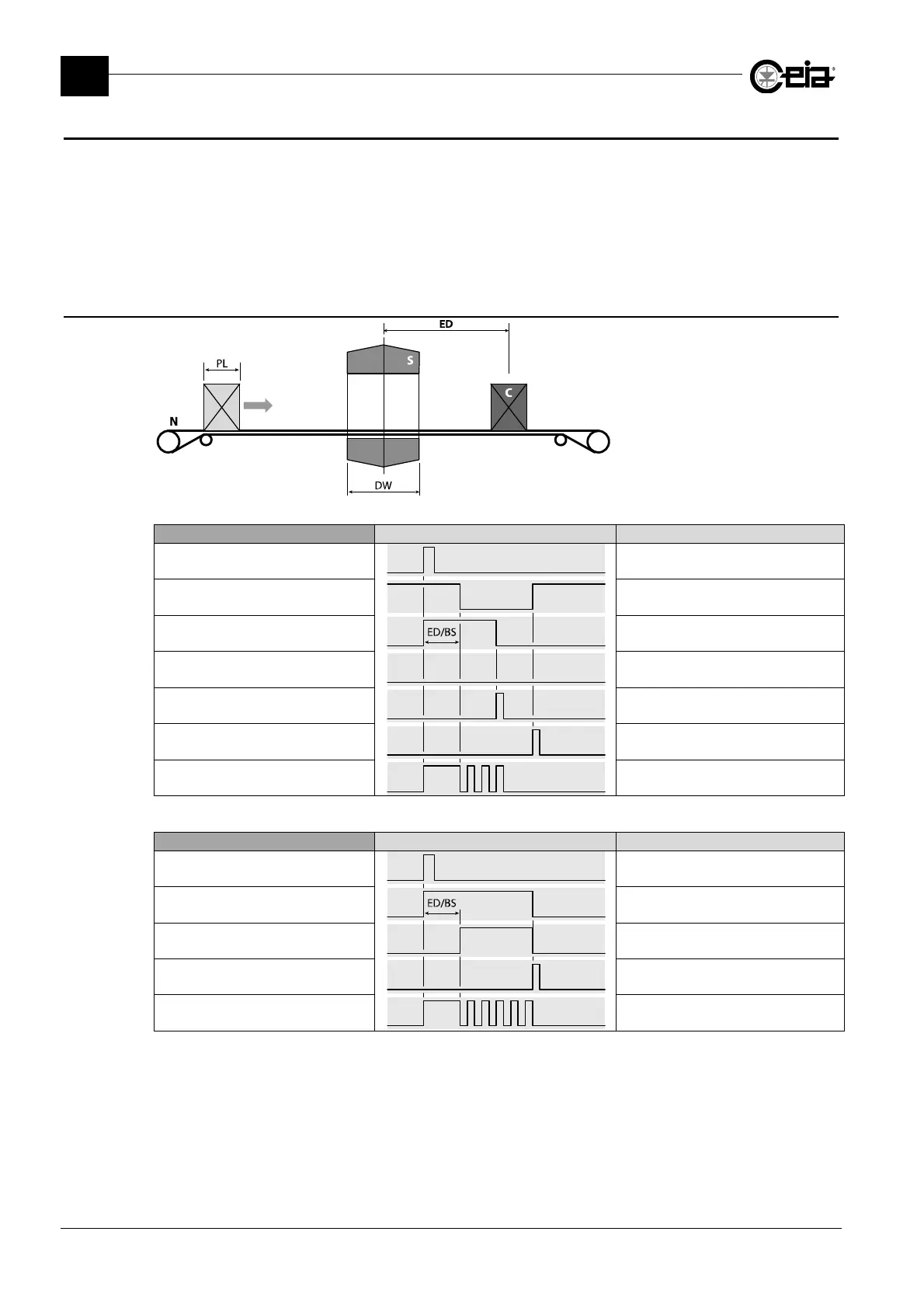
3.9.1 Belt stop (EM=B)
S: Metal Detector probe
N: Conveyor belt
C: Contaminated pack
PL: Pack length
DW: Detector width
ED: Ejector distance
Conveyor Control System Waveform Description
Metal alarm Metal alarm
Conveyor belt movement Conveyor belt movement
Alarm relay (ALARM) External alarm signalling
Ejection relay (EJECT) Not activated
Reset button Alarm reset
Start button Belt restart
Yellow lamp Alarm beacon operation
ED = Stop area distance; BS = Transit speed set on BS parameter or, in presence of an encoder (KE>0), measured
Control Power Box Waveform Description
Metal alarm Metal alarm
Alarm relay (ALARM) External alarm signalling
Ejection relay (EJECT) Product transportation stop
Reset button Alarm reset
Yellow lamp Alarm beacon operation
ED = Stop area distance; BS = Transit speed set on BS parameter or, in presence of an encoder (KE>0), measured