3
FI002K0018v1100UK – THS/21 Instruction manual for installation, use and maintenance
INSTALLATION
70 ORIGINAL INSTRUCTIONS
3.5.8 Connecting to the mains power supply
Only make connections to the internal terminals of the power supply unit when the unit is disconnected from the mains.
If the power supply to the device is different from that specified on the plate, permanent damage may be caused to the
device. CEIA declines all liability for injury to persons and damage to property resulting from failure to follow this
instruction.
Checking that the power supply conforms to the values specified above and to current regulations is the
sole responsibility of the customer.
- Select a cable with wire minimum cross section of 2.5 mm² (AWG14), maximum 4 mm
2
(AWG10) and pass it through the suitably sized cable gland.
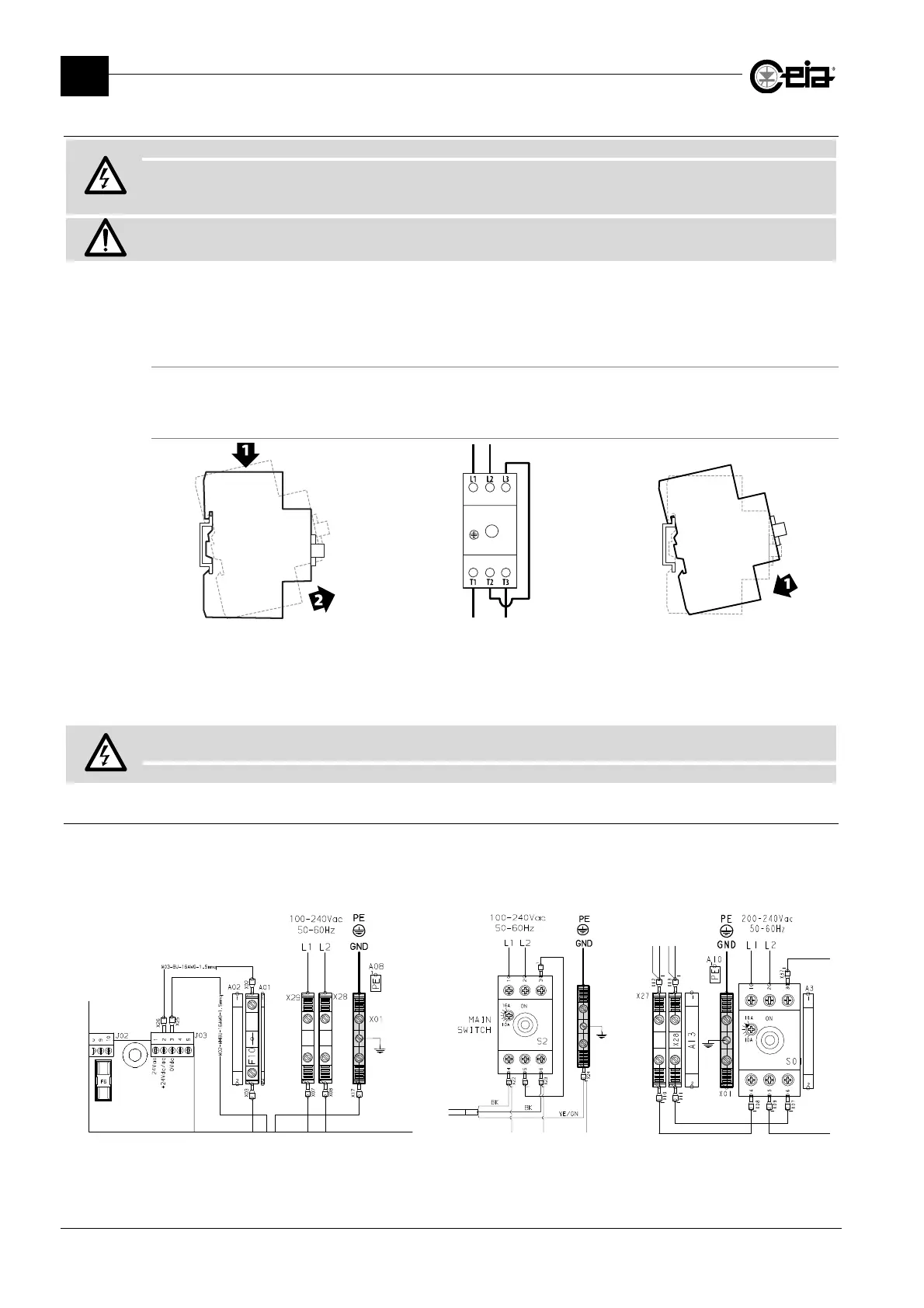
Control Power Box
Connect the mains power supply to the input (L1 and L2) on the terminal block.
Conveyor Control System
Disconnect the terminal block from the
DIN bar by pressing it downwards and
then rotating it upwards.
Connect the mains power supply to
the terminals (L1 and L2) of the
terminal block as shown in this
figure.
Refit the terminal block to the DIN bar
as shown here. Position the cable
inside the enclosure and close the
door.
Install a magnetothermic switch upstream: 250 VAC, max 16 A (on CE applications)
or class CC fuses, max 15 A (on UL applications).
Insert a differential current switch upstream taking care that the trip current is 300 mA
3.5.8.1 Connection to earth
Connect an earthing wire to the PE terminal. The wire size must conform to current safety
standards. Wire cross-section: AWG14 or 2.5 mm
2
, maximum 6 mm
2
(AWG8).
The earth resistance must be lower than that required under the current rules of the country of
installation and, in any case, below 5 ohm.
Control Power Box
Control Power Box with Main
Switch
Conveyor Control System