4
FI002K0018v1100UK – THS/21 Instruction manual for installation, use and maintenance
USE OF THE DEVICE
120 ORIGINAL INSTRUCTIONS
4 USE OF THE DEVICE
Before starting to use the device, carefully read the Safety instructions – Warnings section of this manual
4.1 Indicators
4.1.1 Optical indicators
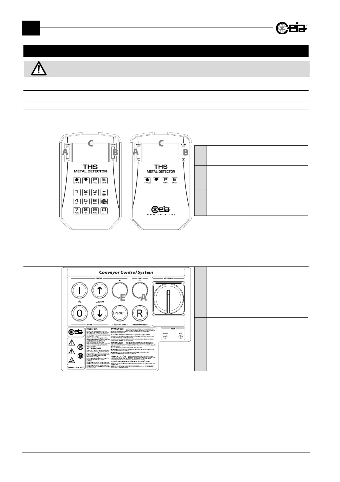
4.1.1.1 Control panel
The control panel, containing the optical indicators and the Metal Detector controls, is located on
the probe or on the power supply box (if fitted with RCU remote control unit):
A
POWER
A green indicator
indicates the
presence of power
B
ALARM
A red indicator
indicates the
detection of a metal fragment
or a fault in the unit
C
Display
Displays the messages
relating to use, programming
and self-diagnosis of the
device
THS/21
Control Panel
THS/21E
Control Panel
4.1.1.2 Conveyor Control System
A
POWER
A white indicator
indicates the
presence of power
E
Conveyor
movement
A green indicator
indicates
that the conveyor is running
1
1
Flashes to indicate that the belt has been stopped by the FOLLOWING CONVEYOR input deactivation and is waiting
to be restarted automatically (see parameter RE, in Programming Manual).