FI002K0018v1100UK – THS/21 Instruction manual for installation, use and maintenance
3
INSTALLATION
ORIGINAL INSTRUCTIONS 69
3.5.7 Connecting a motor (Conveyor Control System only)
Only make connections to the internal terminals of the power supply unit when the unit is disconnected from the mains.
If the power supply to the device is different from that specified on the plate, permanent damage may be caused to the
device. CEIA declines all liability for injury to persons and damage to property resulting from failure to follow this
instruction.
Connect a single triphase asynchronous motor, with plate values compatible with the characteristics of the inverter.
CEIA cannot be held responsible for damage caused by wrong connection of the motor.
The inverter contains high-tension capacitors which discharge slowly when the power supply is shutdown. Before you
work on an inverter, switch off the power supply and wait at least 3 minutes before commencing work.
The inverter must only be programmed from the menu on the local THS programmer.
- Select a cable, with a circular section and screened, with 3 phase and one earth wires
(minimum cross section of 2.5 mm
2
- AWG14). Pass it through the suitably sized cable
gland.
An unscreened cable might cause disturbances to the Metal Detector.
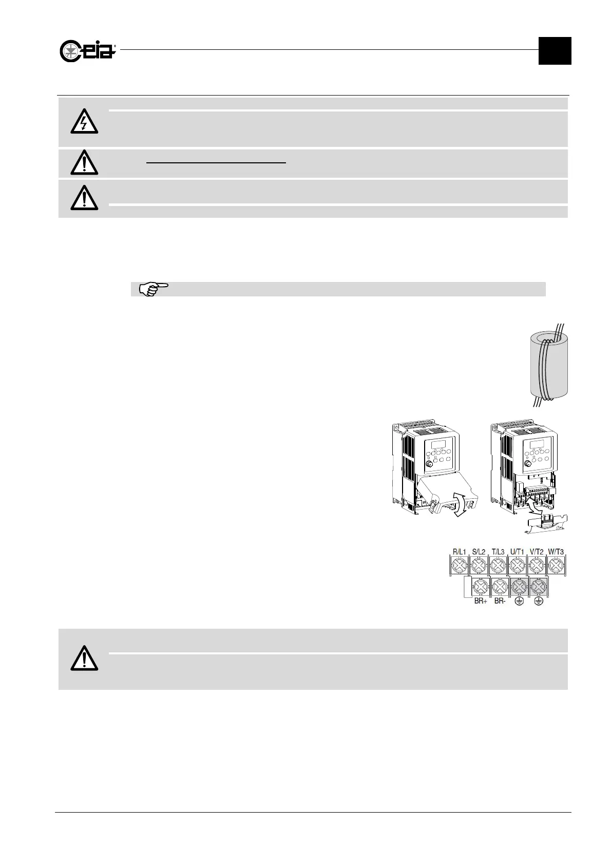
- Take the ferrite supplied and insert the three wires inside as shown to create a
coil. The ferrite must be placed as near as possible to the inverter connection
terminals.
- Open the cover of the inverter terminals as shown
in the figure alongside.
- On the inverter side, connect the phase wires to
the terminals U/T1, V/T2 and W/T3 and connect
the earth wire (and eventually the shield) to the
earth terminal.
- On the motor side, connect the earth wire to the
motor frame. Connect the phases in order to have
a nominal voltage in the 200 - 240 V range.
- Fix the motor cable to the conveyor belt structure,
keeping it as far as possible from the probe
opening.
WARNING! The motor frame must be insulated from the conveyor belt structure and from other metal parts, and earthed
ONLY using the wire connected to the inverter earth terminal.
WARNING! The motor must be installed as near as possible to the probe, depending on its power (see the table in the
General Rules for Electrical Installation). This distance is indicative and also depends on the load conditions and the size
of the probe.