3
FI002K0018v1100UK – THS/21 Instruction manual for installation, use and maintenance
INSTALLATION
116 ORIGINAL INSTRUCTIONS
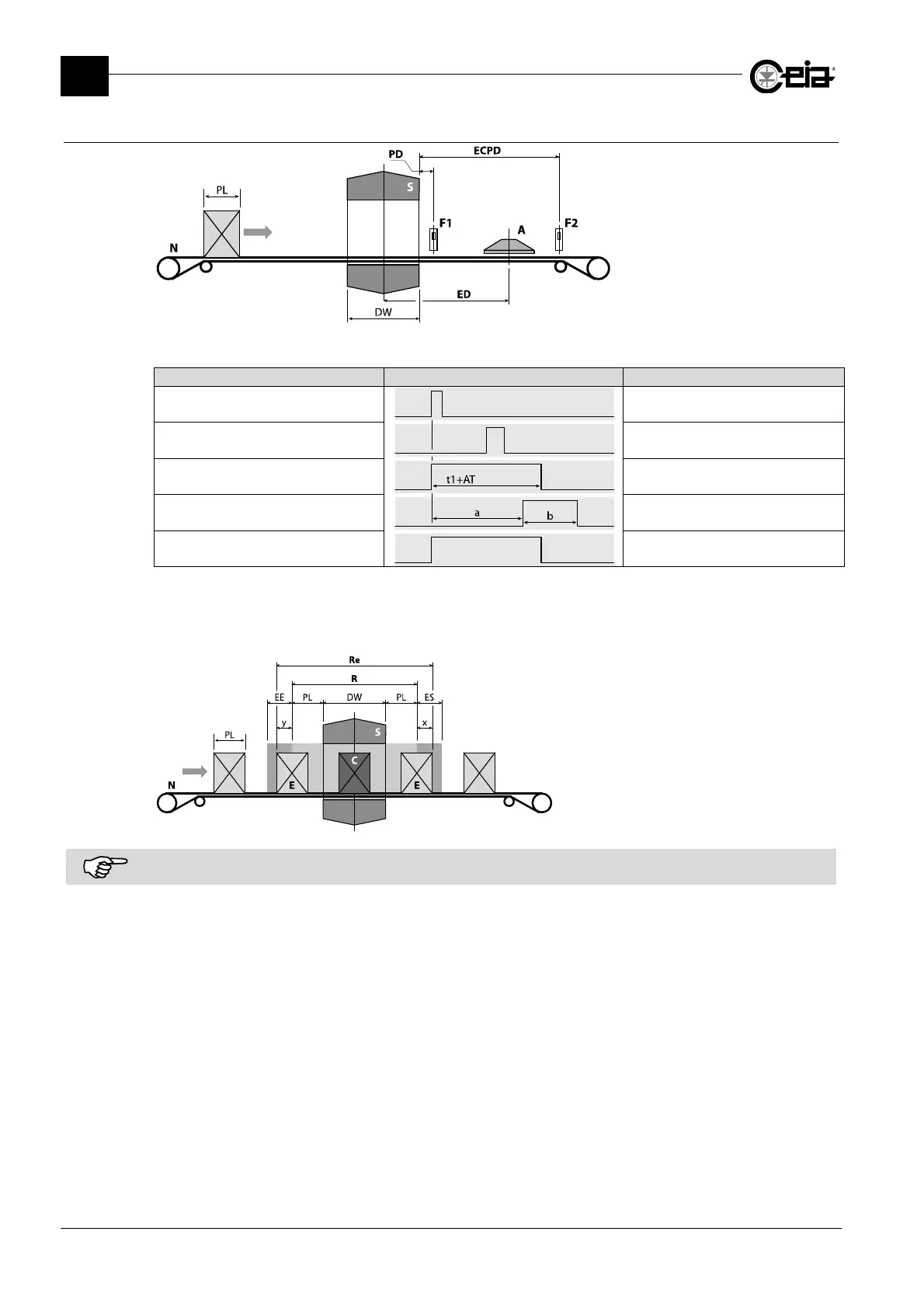
3.9.6 Automatic ejection with photocell synchronization (EM=FS)
S: Metal Detector probe
N: Conveyor belt
A: Air jet ejector
F1: Synchronization photocell
F2: Ejection check sensor
PL: Pack length
DW: Detector width
ED: Ejection distance
PD: Photocell distance
ECPD: Photocell distance
Photocell at the exit (PH=OUT)
Waveform Description
Metal alarm Metal alarm
Photocell
Necessary to calculate areas
x and y
Alarm relay (ALARM) External alarm signalling
Ejection relay (EJECT)
and ejection activation
Ejection
Yellow lamp Alarm beacon operation
AT = Minimum activation time of the alarm relay;
t1 = Alarm time, generally corresponding to the transit of the metal mass through the probe.
a = Calculated automatically to activate the ejector at the start of the removal area R or Re; b = Calculated automatically
for the complete removal of area R or Re.
E: Ejected pack;
C: Contaminated and ejected pack;
EE: Ejection end synchronization area;
ES: Ejection start synchronization area
R: Minimum removal area
Re: Actual removal area
For more accurate adjustment of the delay in activating and/or deactivating the ejector, early and delayed activation can
be adjusted based on the actual activation/deactivation time of the ejector. See the parameters ERT and ERF.