FI002K0018v1100UK – THS/21 Instruction manual for installation, use and maintenance
3
INSTALLATION
ORIGINAL INSTRUCTIONS 115
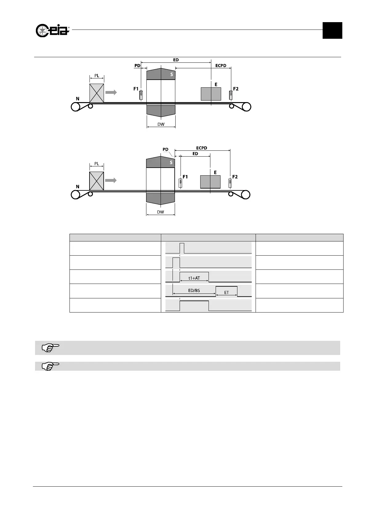
3.9.5 Automatic ejection with photocell synchronization (EM=S)
S: Metal Detector probe
N: Conveyor belt
E: Ejector
F: Synchronization photocell
PL: Pack length
DW: Detector width
ED: Ejection distance
PD: Photocell distance
Photocell at the entrance (PH=IN)
S: Metal Detector probe
N: Conveyor belt
E: Ejector
F1: Synchronization photocell
PL: Pack length
DW: Detector width
ED: Ejection distance
PD: Photocell distance
Photocell at the exit (PH=OUT)
Waveform Description
Metal alarm Metal alarm
Photocell (PH=IN) Synchronization
Alarm relay (ALARM) External alarm signalling
Ejection relay (EJECT) and ejector
activation
Ejection
Yellow lamp Alarm beacon operation
ED = Ejection distance; BS = Transit speed set on BS parameter or, in presence of an encoder (KE>0), measured;
ET = Ejection relay activation time; AT = Minimum activation time of the alarm relay;
t1 = Alarm time, generally corresponding to the transit of the metal mass through the probe.
For more accurate adjustment of the delay in activating and/or deactivating the ejector, early and delayed activation can
be adjusted based on the actual activation/deactivation time of the ejector. See the parameters ERT and ERF.
In Conveyor Control Systems, or with encoder installed, the ejection cycle occurs only when the belt is moving.