FI002K0018v1100UK – THS/21 Instruction manual for installation, use and maintenance
3
INSTALLATION
ORIGINAL INSTRUCTIONS 99
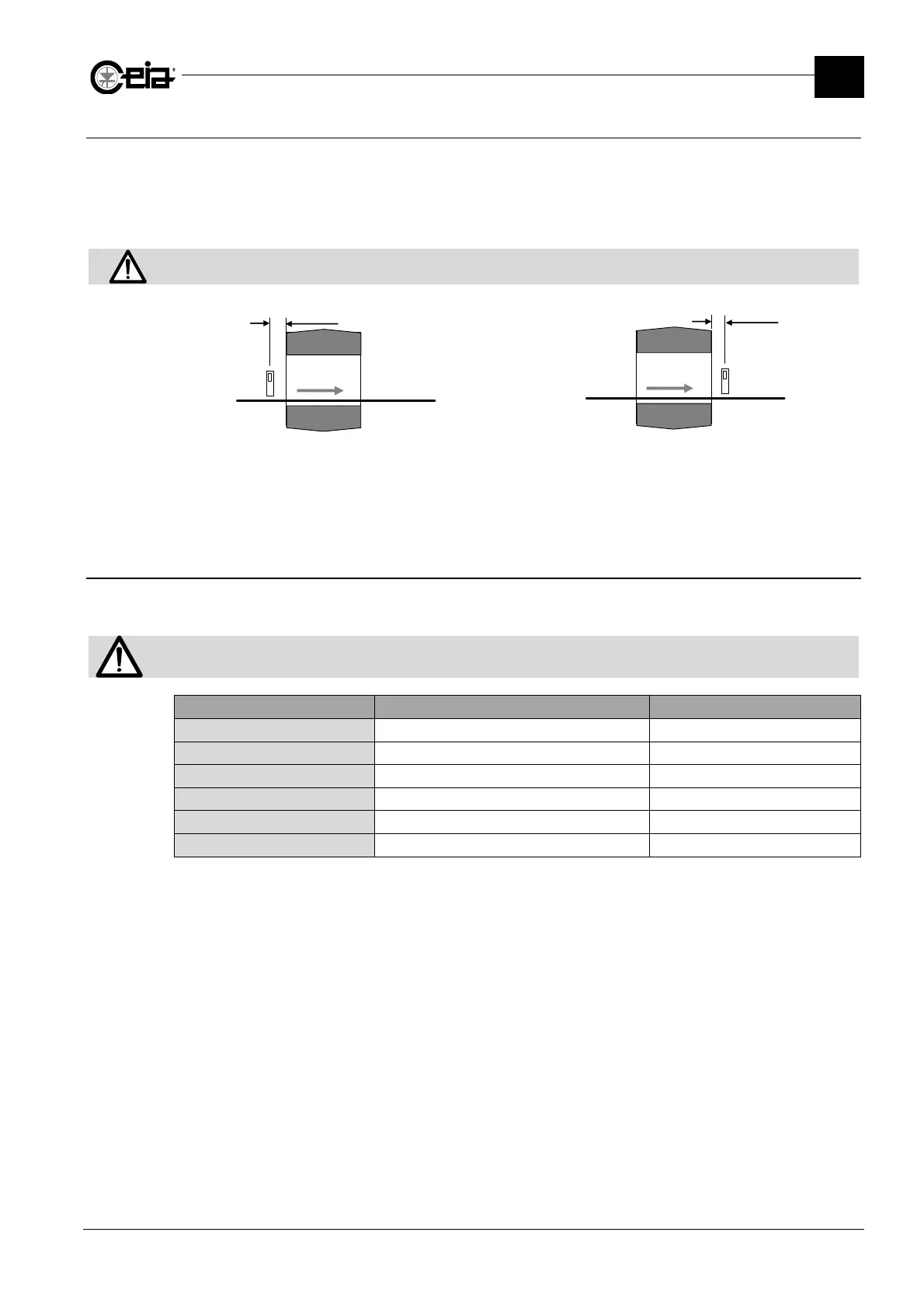
3.7.5 Synchronization photocell
The Synchronization photocell enables a high degree of precision in ejecting contaminated material
and counting the product transiting through the unit.
Install the photocell as close as possible to the Metal Detector antenna at the entrance or the exit in
the direction of transit depending on the ejection mode used.
The photocell must be connected to the PHOTOCELL input.
The photocell must be positioned at a height where the beam is always interrupted by the objects transiting on the
conveyor belt.
F
S
N
PD
F
S
N
PD
Photocell installed at the entrance
Photocell installed at the exit from the probe
N: conveyor belt; S: electronics unit; F: photocell; PD: distance photocell- electronics unit
Install the photocell as close as possible to the antenna entrance.
3.7.6 Connection to other in-line devices or machines
The power supply card relays can be connected to external devices, according to the operation
required in the production line.
For systems installed in the line, the READY RELAY should be connected in order to guarantee the appropriate actions on
the production line, in case of a fault with the Metal Detector.
Relay Signal (with activated relay) Contact (with activated relay)
READY RELAY Metal Detector operative C-NO
ALARM RELAY Metal alarm C-NO
EJECT RELAY Ejection C-NO
TEST REQUEST RELAY Test request or Running Test
C-NO
AUX RELAY Specific status of the Metal Detector
C-NO
PREC CONV RELAY
Belt in movement C-NO
1
The opposite logic can also be selected
2
Only with Conveyor Control System or encoder
3
Programmable