FI002K0018v1100UK – THS/21 Instruction manual for installation, use and maintenance
3
INSTALLATION
ORIGINAL INSTRUCTIONS 95
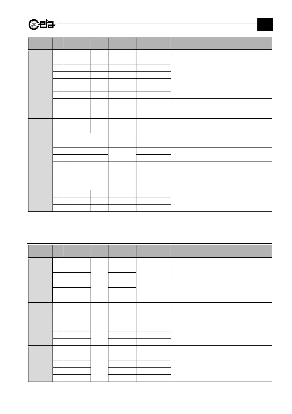
Connector Pin Label IN/OUT Type
Range/Max.
value
Function
J18
1
1 GND GND
Connection of the beacon and horn
2 0V 0 V
3 RED LAMP Output Fault signal 0/24V
4 YELLOW L. Output Alarm signal 0/24V
5 BLUE LAMP Output
Test req.
signal
0/24V
6 HORN Output Sound signal 0/24V
7 SPARE LAMP
Output
Reset
backlight
0/24V
Backlighting of external button connected to the
RESET input, activated by the Reset request
8 WHITE L. Output Main signal 24V
J19
1
1 GND GND
2 0V 0 V
3 EXT EM BUTTON
EXT EM
BUTTON
External emergency button (NC single contact)
If not used, keep jumpered
4 EXT EM BUTTON
5 EM STOP 1A
EM STOP 1
External emergency button connections (NC double
contact) 1 of 2. If not used, keep jumpered
6 EM STOP 1B
7
K1 NC -
Reserved for connection to relay K1.
With Control Power Box, keep jumpered.
8
9 EM STOP 2A
EM STOP 2
External emergency button connections (NC double
contact) 2 of 2. If not used, keep jumpered
10 EM STOP 2B
11 -
Reserved
12 -
13 -
1
Connector not present on Control Power Box – basic version
3.7.2 00211AL_ card
Connector Pin Label IN/OUT Type
Range/Max.
value
Function
J1
1 C
Output
common
30 V AC/DC 2.5A
Ready relay
2 NC N.C. contact
3 NO N.O. contact
4 C
Output
common
Ejector relay
5 NC N.C. contact
6 NO N.O. contact
J2
1 GND
Reserved
GND
Reserved for RCU connection
2 GND GND
3 TXD Data
4 RXD Data
5 +5V +5 V
6 +V +24 V
J3
1
-
+24 V 100 mA max
RS-232 serial connection
The 24 V on pin 1 is present only if the minidip VRS232
of switcher SW1 is set to ON. By default it is set to
OFF.
2 RXD
3 TXD
5 0 V
6 DTR