3
FI002K0018v1100UK – THS/21 Instruction manual for installation, use and maintenance
INSTALLATION
94 ORIGINAL INSTRUCTIONS
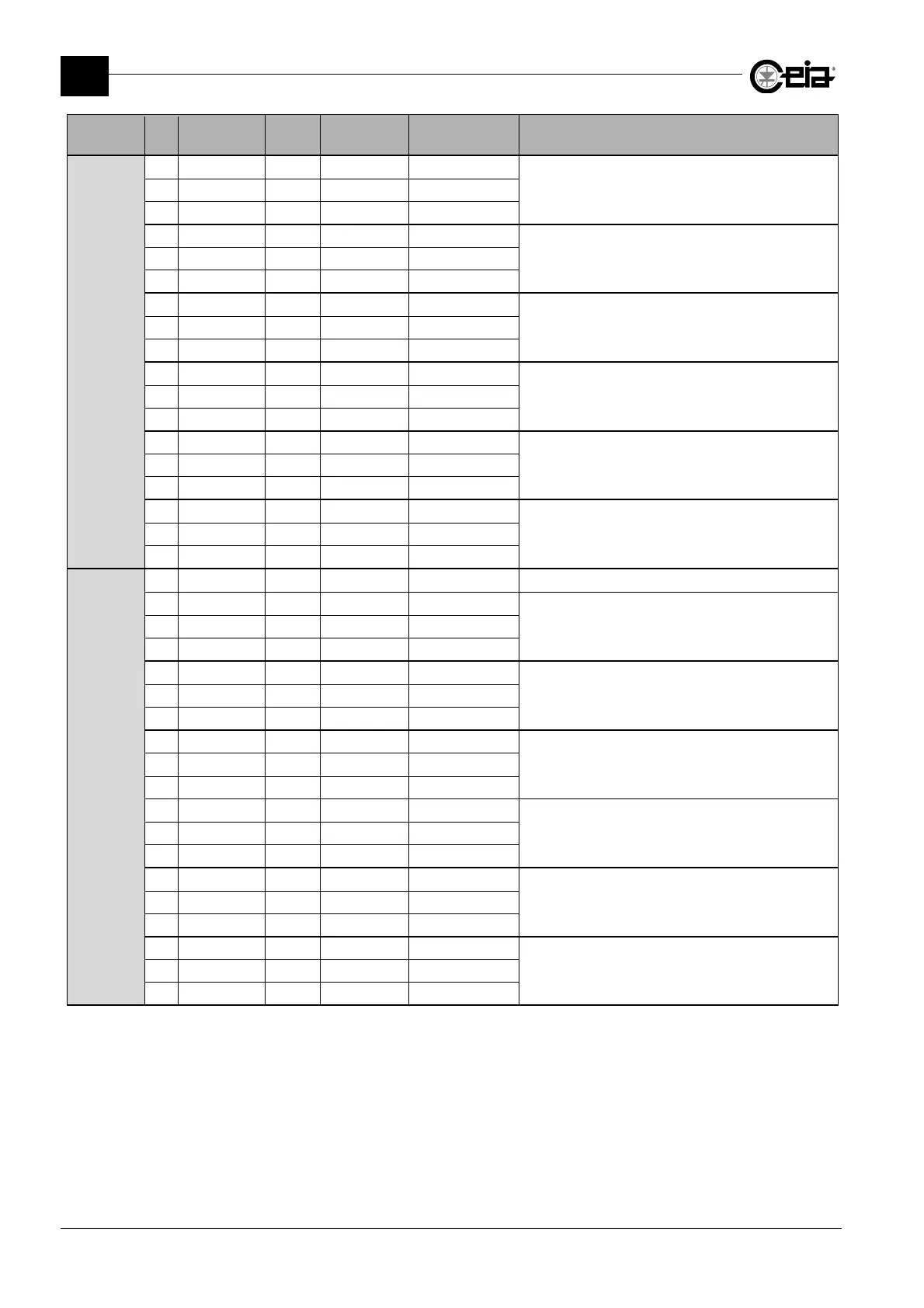
Connector Pin Label IN/OUT Type
Range/Max.
value
Function
J16
1
1 0V 0V
Connection of ejection system check sensor
2 Ej. check Input
3 +Vin 24V
2
4 0V 0V
Connection of ejector position check sensor
5 EJ.POS. CHK Input
6 +Vin 24V
2
7 0V 0V
Connection of a button (NA) to activate Test
request
8 IN AUX1 Input
9 +Vin 24V
2
10 0V 0V
Connection of bin absent sensor
11 Bin absent Input
12 +Vin 24V
2
13 0V 0V
Connection of Metal Detector inhibition signal
14 Inhibition Input
15 +Vin 24V
2
16 0V 0V
Connection for Following Conveyor enabling signal
17 Foll.Conv. Input
18 +Vin 24V
2
J17
1 GND
2 0V 0V
Connection of bin full level sensor
3 BIN FULL Input
4 +Vin 24V
2
5 0V 0V
Connection of an encoder
Maximum pulse frequency: 3 kHz
Type: push-pull 24 V
6 Encoder Input
7 +Vin 24V
2
8 0V 0V
Connection of a low pressure sensor
9 Low pressure
Input
10 +Vin 24V
2
11 0V 0V
Connection of a reset pushbutton (NO)
12 Reset Input
13 +Vin 24V
2
14 0V 0V
Connection of the synchronization photocell
15 Photocell Input
16 +Vin 24V
2
17 0V 0V
Connection of ejection confirmation sensor
18 EJ.CONFIRM Input
19 +Vin 24V
2
1
Connector not present on Control Power Box – basic version
2
The +Vin power supply can provide an overall maximum current of 150mA.