FI002K0018v1100UK – THS/21 Instruction manual for installation, use and maintenance
2
DESCRIPTION
ORIGINAL INSTRUCTIONS 31
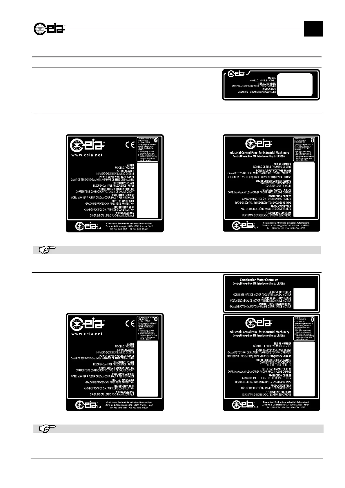
2.4 Device identification
2.4.1 Probe
All antennas including those fitted to integrated
systems have ID plates showing the following data:
Model and Serial number of the antenna and
Dimensions of the tunnel.
xxxxxx
211002xxxxx
300 x 150
2.4.2 Control Power Box
All control power boxes including those fitted to integrated system have ID plates with the
information shown in the examples below.
211002xxxxx
200 – 240 Vac
50/60 Hz – 1ph
x kA rms Symmetrical
xx V max
XX,X A
IP65
2011
E2xxx
T/MS21
211002xxxxx
100 – 240 Vac
50/60 Hz – 1ph
5 kA rms
Symmetrical
240 V max
X.X A
IP65
4X
2011
E2xxx
ID plate for CE models ID plate for UL508A models
The ID plates above are provided as examples only. The values shown vary from model to model.
2.4.3 Conveyor Control System
211002xxxxx
200 – 240 Vac
50/60 Hz – 1ph
x kA rms Symmetrical
xx V max
XX,X A
IP65
2011
E2xxx
T/21
THS/FBB
X.
XXX Vac
XX Hp
211002xxxxx
100 – 240 Vac
50/60 Hz – 1ph
5 kA rms
Symmetrical
240 V max
X.X A
IP65
4X
2011
E2xxx
ID plate for CE models ID plate for UL508A models
The ID plates above are provided as examples only. The values shown vary from model to model.