FI002K0018v1100UK – THS/21 Instruction manual for installation, use and maintenance
3
INSTALLATION
ORIGINAL INSTRUCTIONS 61
3.3 Mechanical installation
3.3.1 Probe
Insert the probe onto the structure of the production line (or onto the pipe carrying the material to
be inspected, in the case of THS/G21x models) and fix it with screws and plastic spacers, using the
holes provided on the underside.
For the fixing distances see the Dimensions section for the relevant model, in chapter 2 –
Description of this manual.
For antennas with a rectangular opening, fasten the antenna with the holes in the support feet,
using screws of the appropriate length which never come into contact with the antenna frame.
WARNING! The Metal Detector antenna with rectangular opening is fitted with appropriate insulated support feet. The
antenna structure is connected to earth with the connection cable with the power supply unit; it must not be connected
to other metal parts and the support feet must always be insulated.
The power supply unit must be firmly attached to the load-bearing structure by means of four
screws. It must be close to the central electronics unit and to the external accessory devices
connected to the unit (photocell, ejector, etc.).
For the fixing distances see the Dimensions section for the relevant model, in chapter 2 –
Description of this manual.
During the installation procedure, if the connection cable between the probe and the power supply
box needs to be disconnected, do it from the power supply box side and not from the probe side.
This operation requires the terminals to be disconnected from the connector connected to the ALM
card and the screen to be disconnected from the earth screw on the bottom of the container.
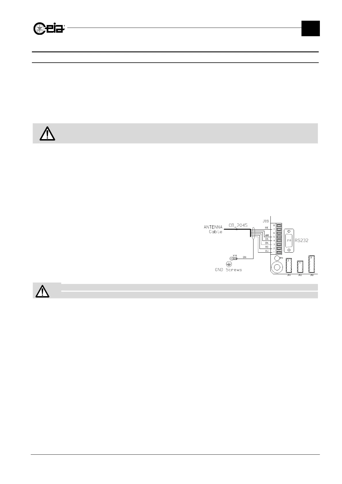
After the antenna and the Power Supply Unit have
been positioned correctly, put the cable back in
the Power Supply Unit through its cable gland,
reconnect the screen to the earth screw,
reconnect the terminals to the connector, following
the exact order of the colours (see figure
alongside) and put the connector back on the
ALM card.
Fix the probe cable to the power supply unit so that it cannot oscillate or vibrate.
If the cable is too long, DO NOT CUT THE CABLE: COIL UP THE EXCESS inside the power supply box.