FI002K0018v1100UK – THS/21 Instruction manual for installation, use and maintenance
3
INSTALLATION
ORIGINAL INSTRUCTIONS 93
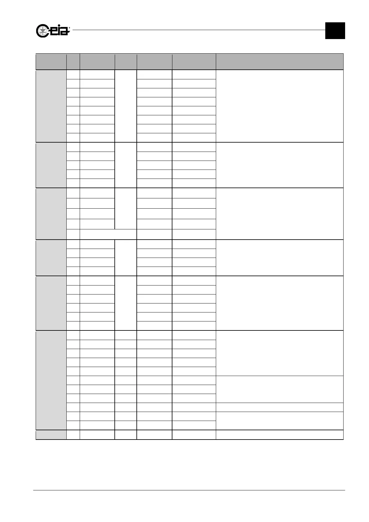
Connector Pin Label IN/OUT Type
Range/Max.
value
Function
J09
1 BU
Reserved
-16V
Reserved for the antenna connection
2 RD +16V
3 BN +5.6V
4 GN GND
5 WH Data
6 -
7 BK Data
8 -
J10
1
-
+24V 100 mA max
RS-232 serial connection
The 24 V on pin 1 is present only if the minidip VRS232
of switcher SW1 is set to ON. By default it is set to
OFF.
2 RXD
3 TXD
5 0 V
6 DTR
J11
1
1 GND
-
GND
Barcode reader connection
If the Barcode reader connected needs a current hi
her
than 150 mA, an external power supply must be used
leaving pin 5 disconnected.
2 GND GND
3 RXD Data
4 TXD Data
5 +24V BC Reader +24V 150 mA max
J12
1 GND
-
GND
Auxiliary serial port communication
2 TXD Data
3 RXD Data
4 +V +24V 150 mA max
J13
1 GND
Reserved
GND
Reserved for RCU connection
2 GND GND
3 TXD Data
4 RXD Data
5 +5V +5V
6 +V 24V
J14
1 GND GND
2 0V 0V
3 0V 0V
4 Vout
2
Output 24V
5 Vout
2
Output 24V
6 Vdd
Reserved
7 -
8 -
9 0V 0V
10 Ejector NO
2,3
Output 0 ÷ Vout
Ejection system connection
11 Ejector NC
2,3
Output 0 ÷ Vout
J15
Reserved
1
Connector not present on Control Power Box – basic version
2
The output can provide an overall maximum current of 150 mA. In case of an emergency, the output is set to 0 V.
3
Ejector driving: Ejector NO: NO solenoid valve driving; Ejector NC: NC solenoid valve driving.