3
FI002K0018v1100UK – THS/21 Instruction manual for installation, use and maintenance
INSTALLATION
96 ORIGINAL INSTRUCTIONS
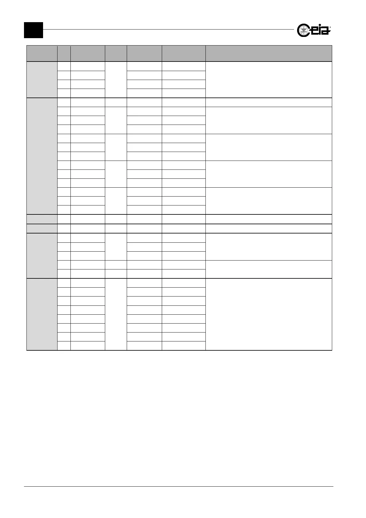
Connector Pin Label IN/OUT Type
Range/Max.
value
Function
J4
1 GND
-
GND
Auxiliary serial port communication
2 TXD Data
3 RXD Data
4 +V +24 V 150 mA max
J5
1 GND
2 +Vin
Input
24V
Connection of ejection confirmation sensor
3 EJ.CONFIRM
4 0V 0V
5 +Vin
1
Input
24V
Connection of the synchronization photocell
6 Photocell
7 0V 0V
8 +Vin
1
Input
24V
Connection of a reset push-button
9 Reset
10 0V 0V
11 +Vin
1
Input
24V
Connection of an encoder
12 ENCODER
13 0V 0V
J6
Reserved
J7
Reserved
J8
1 24 Vac
Input
24 Vac 20 – 30 V
24 V power supply input from AC/DC converter
2 +24 Vdc/ac +24 Vdc/ac
3 0 Vdc 0 Vdc
4 - - - -
Reserved
5 - - - -
J9
1 BU
Reserved
-16V
Reserved for the antenna
2 RD +16V
3 BN +5,6V
4 GN GND
5 WH Data
6 -
7 BK Data
8 -
1
The +Vin power supply can provide an overall maximum current of 150mA.