FI002K0018v1100UK – THS/21 Instruction manual for installation, use and maintenance
3
INSTALLATION
ORIGINAL INSTRUCTIONS 53
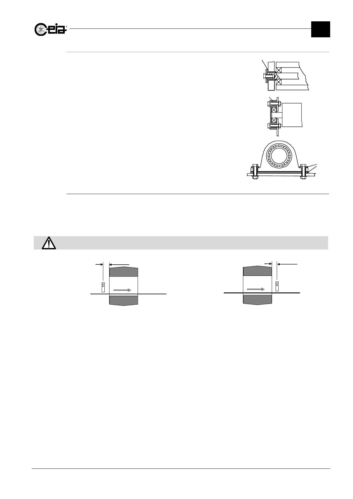
Examples of roller insulation
Insulation of the roller pin.
R: roller;
I: ferrule made from insulating material;
P: side bulkhead of the belt frame;
Insulation of the roller pin support.
R: roller;
I: bearing support made from insulating material;
P: side bulkhead of the belt frame;
Insulation of the bearing support of a roller pin.
I: ferrule and spacer in insulating material.
3.1.2.3.5 Synchronization photocell
The Synchronization photocell enables a high degree of precision in ejecting contaminated material
and counting the product transiting through the unit.
Install the photocell as close as possible to the Metal Detector antenna at the entrance or the exit in
the direction of transit depending on the ejection mode used (see paragraph 3.8.8).
The photocell must be connected to the PHOTOCELL input.
The photocell must be positioned at a height where the beam is always interrupted by the objects transiting on the
conveyor belt.
F
S
N
PD
F
S
N
PD
Photocell installed at the entrance
Install the photocell as close as possible to the antenna
entrance.
Photocell installed at the exit from the probe
Install the photocell as close as possible to the antenna
exit.
N: conveyor belt; S: electronics unit; F: photocell; PD: distance photocell- electronics unit;
I
P
R
I
P
R
I