CI Systems SR-800R
4. Connect cables:
a. Connect the HEAD cable between the SR-800R-HEAD connector and the
Blackbody connector (see Figure 4-2).
b. Connect all the other cables you might use (such as AXES 1/2, AXES 3/4,
I/O, LAN, RS232, and GPIB).
c. Connect the power cable between the SR-800R-110/230V connector and
Mains (see Figure 4-2).
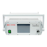
Figure 4-2: Connectors
110/230VF12.5AI/ORS232GPIB
LAN
HEAD
AXES 1/2 AXES 3/4
Now you have completed installation of the SR-800R as a portable unit. The SR-800R
is ready for operation.
For information on how to use and operate the SR-800R, refer to Chapter 3 of this
manual.
CAUTION
Power-off the SR-800R before disconnecting or replacing any
SR-800R cable. Failure to comply may result in damage to
equipment.
605-7040 Operation Manual
Rev D 4-3
June 2013
Artisan Technology Group - Quality Instrumentation ... Guaranteed | (888) 88-SOURCE | www.artisantg.com