5-15
Software Configuration Guide—Release IOS XE 3.6.0E and IOS 15.2(2)SG
OL-30933-01
Chapter 5 Configuring Virtual Switching Systems
Understanding Virtual Switching Systems
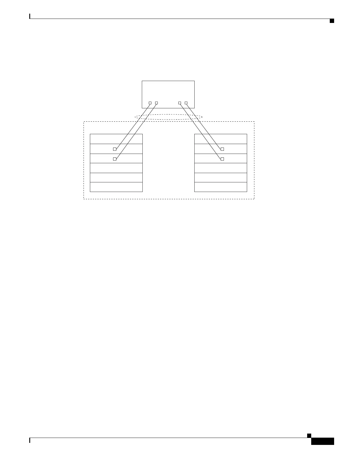
An MEC can support up to eight physical links, which can be distributed in any proportion between the
VSS Active and VSS Standby switch.
Figure 5-7 MEC Topology
MEC Failure Scenarios
We recommend that you configure the MEC with at least one link to each switch. This configuration
conserves VSL bandwidth (traffic egress link is on the same switch as the ingress link), and increases
network reliability (if one VSS supervisor engine fails, the MEC is still operational).
The following sections describe possible failures and the resulting impacts:
• Single MEC Link Failure, page 5-15
• All MEC Links to the VSS Active Switch Fail, page 5-15
• All MEC Links to the VSS Standby Switch Fail, page 5-16
• All MEC Links Fail, page 5-16
• VSS Standby Switch Failure, page 5-16
• VSS Active Switch Failure, page 5-16
Single MEC Link Failure
If a link within the MEC fails (and other links in the MEC are still operational), the MEC redistributes
the load among the operational links, as in a regular port.
All MEC Links to the VSS Active Switch Fail
If all links to the VSS Active switch fail, the MEC becomes a regular EtherChannel with operational
links to the VSS Standby switch.
Data traffic terminating on the VSS Active switch reaches the MEC by crossing the VSL to the VSS
Standby switch. Control protocols continue to run in the VSS Active switch. Protocol messages reach
the MEC by crossing the VSL.
Virtual switch
Supervisor
engine
Supervisor
engine
Active chassis Standby chassis
181327
Router, switch
or server
MEC

 Loading...


